Jun 30, 2026
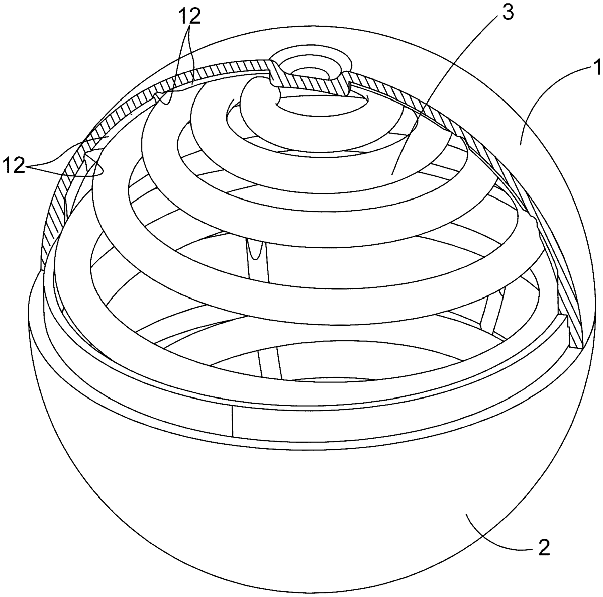
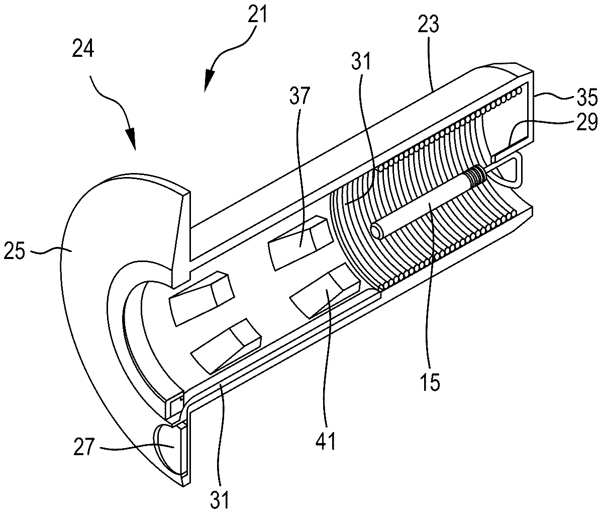
The present invention provides a counterweight projectile having an upper hemispherical shell and a lower hemispherical shell and each having a plurality of grooves on the inner surface thereof, wherein a hollow space is formed in the combined upper and lower hemispherical shells used to contain a spherical content. The counterweight projectile includes a spherical spring accommodated in the hollow space. The spherical spring is in a shape of a plurality of coils wound along the inner surfaces of the upper and lower hemispherical shells, and is completely supported and held on the inner surfaces of the hemispherical shells. After ejecting, the counterweight projectile which has a matching weight to shoot forward, stably, straight and evenly to an impact point, after contacting the impact point, the spherical spring is squeezed and restored to explode the upper and lower hemispherical shells, and increases the explosion and spread of the spherical content.
Jun 30, 2026
A ceramic substrate including a porous internal structure including a sealant infiltrator. The sealant infiltrator includes sodium and silicate. The sealant infiltrator infiltrates at least some of the plurality of pores and closes the plurality of pores filled with the sealant infiltrator when exposed to a negative pressure. The sealant infiltrator is distributed across the exterior surface of the ceramic substrate.
Jun 30, 2026
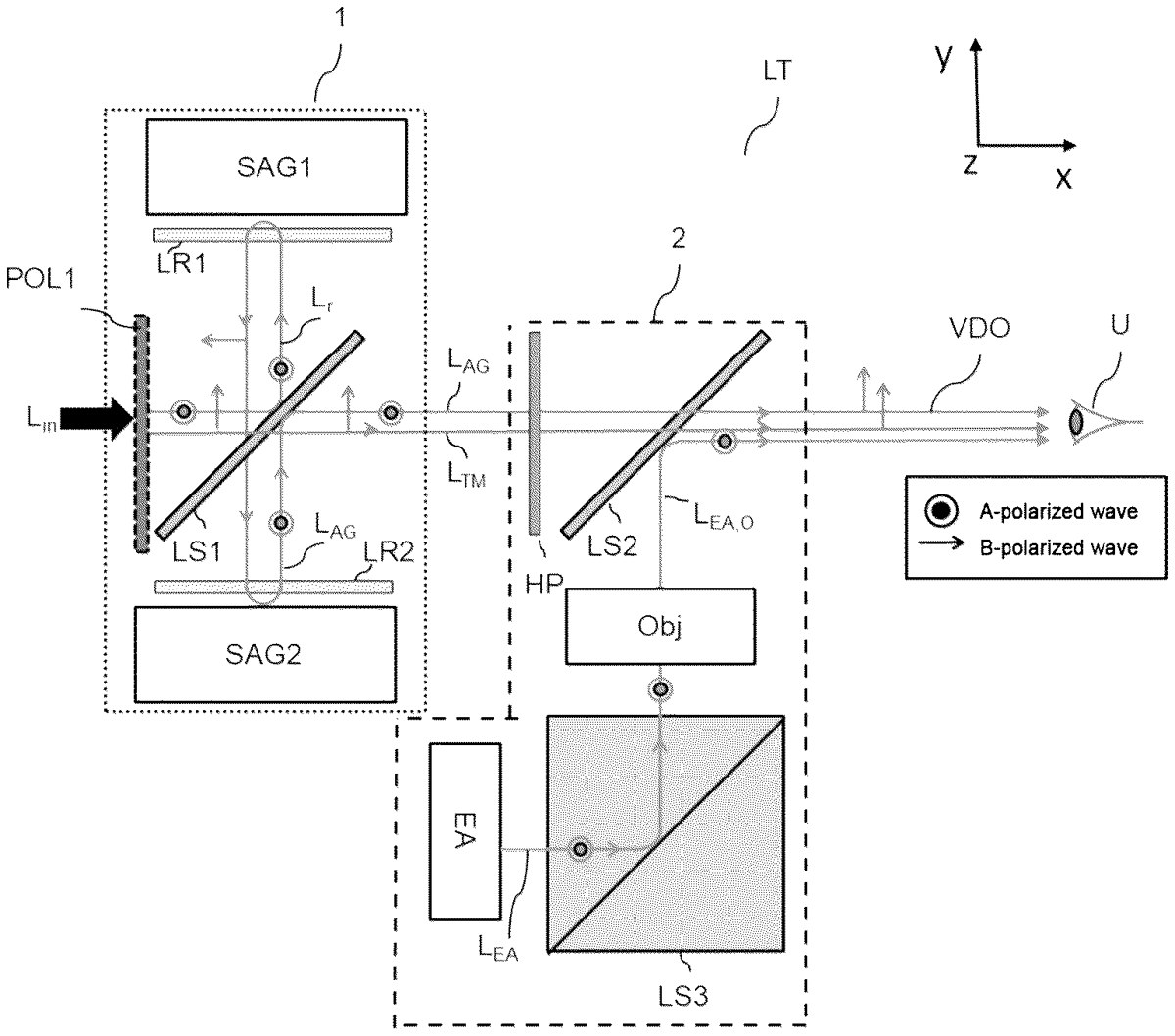
A scope observing a scene includes a first optical sub-assembly, being an afocal module, and a second optical sub-assembly, being a display module. The afocal module includes: a removable and switchable linear polarizer, a first polarization-splitting element, and an afocal optical system arranged to collect light reflected by the first polarization-splitting element. The display module includes: a half-wave plate, being a distribution plate, a display, an optical objective to collimate the display light; and a second polarization-splitting element arranged after the distribution half-wave plate.
Jun 30, 2026
Jun 30, 2026
Jun 23, 2026
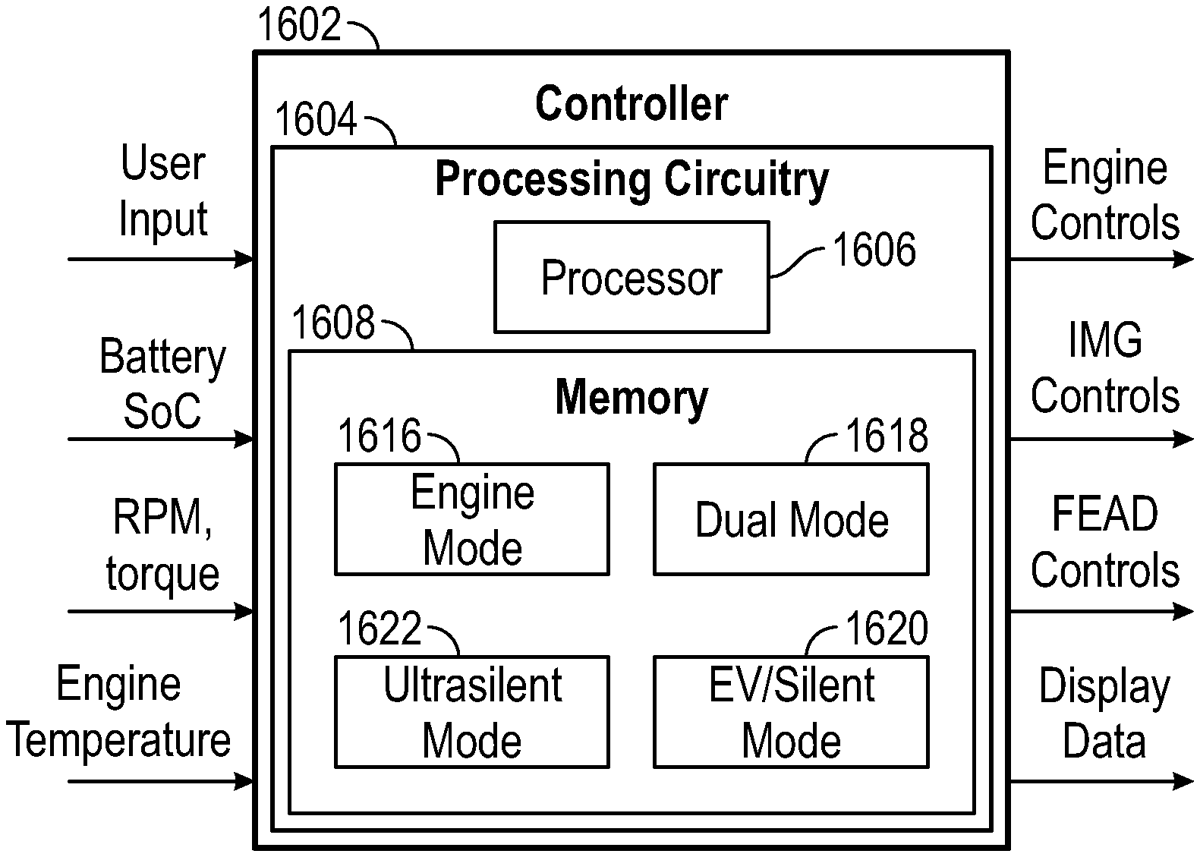
A military vehicle includes a chassis, a front end accessory drive (FEAD), and circuitry. The chassis includes an engine and an integrated motor generator (IMG). The FEAD includes multiple accessories and an electric motor-generator. The circuitry is configured to operate the military vehicle according to different modes. The circuitry is configured to receive a user input indicating a selected mode of the modes, and operate the chassis and the FEAD of the military vehicle according to the selected mode. The modes include an engine mode and an electric mode. In the engine mode, the engine drives the FEAD and the tractive elements of the military vehicle through the IMG for transportation. In the electric mode, the engine is shut off to reduce a sound output of the military vehicle and the IMG drives the tractive elements of the military vehicle for transportation and the electric motor-generator drives the FEAD.
Jun 23, 2026
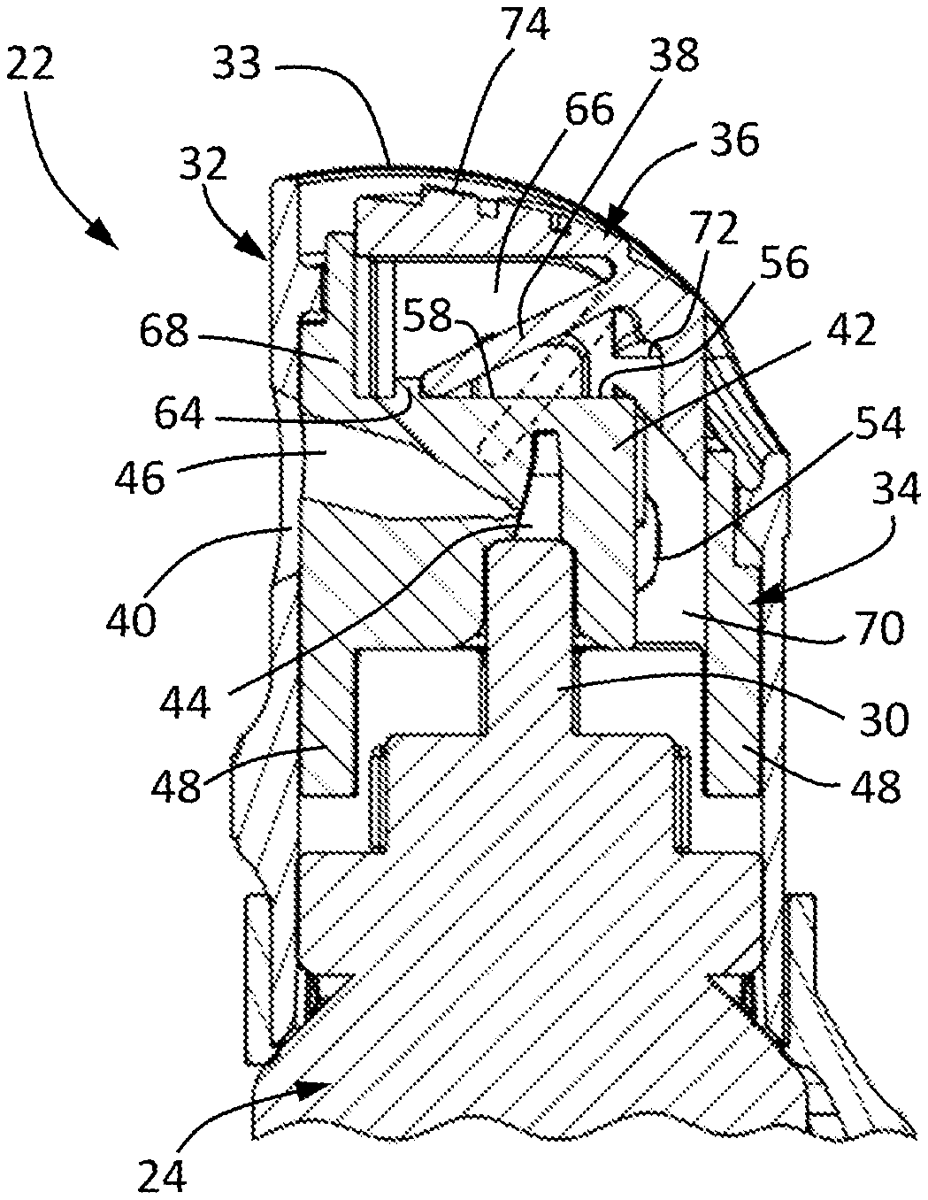
Dispensing systems, dispensers, and methods for dispensing a pepper spray or other irritant from a container. Such dispensers include a cap, a nozzle within the cap so as to be translatable relative to the cap, an actuator within the cap so as to be translatable relative to the cap and relative to the nozzle, and a biasing member that urges the actuator and nozzle apart. The nozzle is configured to attach to a valve stem of a canister and has a passageway through which the pepper spray is dispersed. The dispenser has a partially actuated position following a first actuation stage resulting from the actuator being translated until the actuator abuts the nozzle without causing the nozzle to translate, and a fully actuated position following a second actuation stage resulting from the actuator being further translated to cause the nozzle to simultaneously translate with the actuator.
Jun 23, 2026
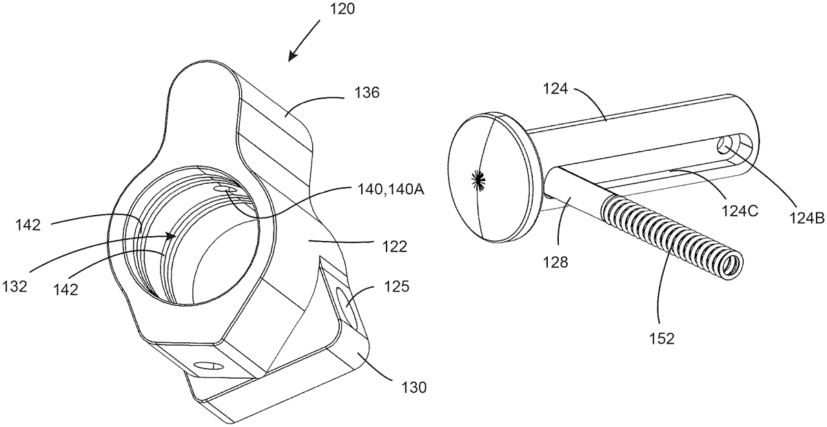
A firearm gas block assembly includes a gas block having a central bore and a retention member passage. The gas block engages a gas block journal of a barrel via the central bore. The retention member passage intersects the central bore to define an opening between the central bore and the retention member passage. A retention member within the retention member passage is moveable between first and second positions. A portion of the retention member extends through the opening when in the first position. No portion of the retention member extends through the opening when in the second position. Gas flow control discontinuities are within a surface of the gas block defining the central passage. A travel limiting member is engaged with the retention member and the gas block for limiting axial movement of the retention member to being between the first and second positions.
Jun 23, 2026
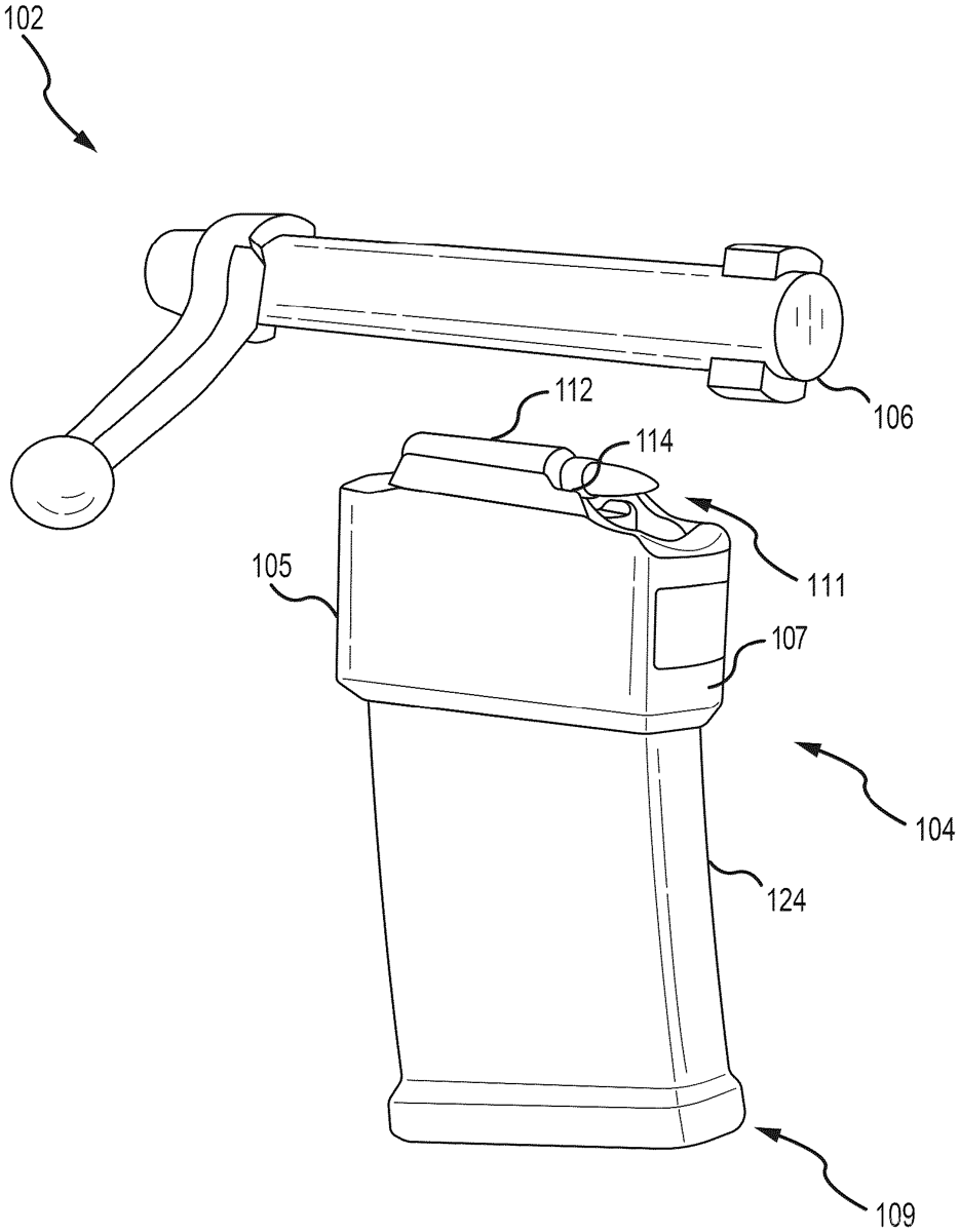
This disclosure describes systems, methods, and apparatus for a magazine assembly for a firearm, the magazine assembly comprising: an elongated housing, a spring positioned in an interior of the housing, a first and second plate at a proximal end of the housing, at least one follower configured to support one or more cartridges and move or slide within the housing based on a compression and decompression of the spring, one or more feed lips positioned at a distal end of the housing, the one or more feed lips adapted to prevent upward movement of a topmost of the one or more cartridges until a bolt or slide chambers the topmost of the one or more cartridges, and wherein the topmost cartridge is arranged off-center from the bolt of the firearm so as to increase an engagement or overlap between the bolt and the topmost cartridge.
Jun 23, 2026
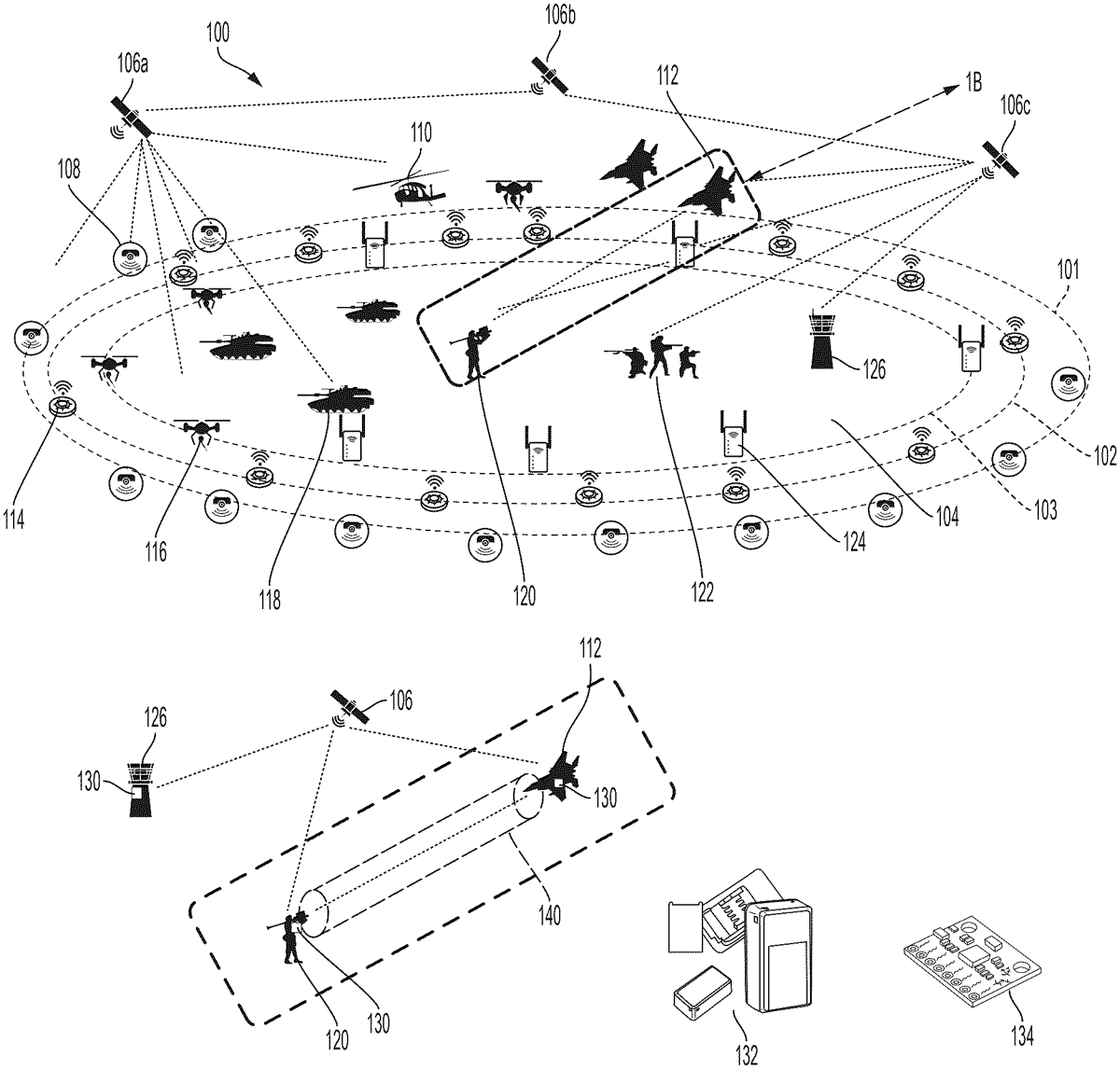
Apparatus, systems, and methods for advanced battlefield command and control systems (“ACCS”) are disclosed herein. The ACCS operates primarily by communication between closed-loop identification devices (“CIDD”) configured to be integrated into weapons systems and as wearable components on fatigues of soldiers. The CIDDs include sensors such as gyroscopes and GPS locators which send information to an area command and control (“AC2”) unit which sends commands to the CIDDs of the weapons systems. The information from the sensors is used to establish safe zones between CIDDs and determine whether a line of fire of the weapons system overlaps the safe zone. If the line of fire overlaps the safe zone, the CIDD is configured to prevent the weapons system from firing and alert an operator of the overlap.
Jun 23, 2026
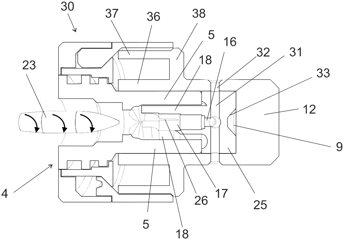
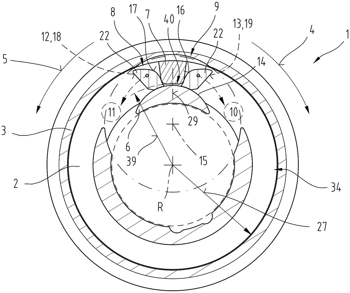
A firearm attachable bullet trap ( 2 ) including a hollow body ( 3 ) configured to be releasable connected a muzzle end ( 7 ) of a rifle barrel ( 8 ) of a firearm ( 1 ). The hollow body ( 3 ) defining a ballistic plate chamber ( 9 ). The firearm attachable bullet trap ( 2 ) including a ballistic plate ( 12 ) in the ballistic plate chamber ( 9 ), and a bullet deforming part ( 14 ) within the hollow body ( 3 ), wherein the bullet deforming part ( 14 ) has a central channel ( 15 ), wherein the central channel ( 15 ) having a central axis A. The central channel ( 15 ) of the bullet deforming part ( 14 ) includes an open-sided channel section ( 17 ) that is radially limited by stationary cutter blades ( 18 ), wherein each stationary cutter blade ( 18 ) has a second proximal end ( 19 ) and a second distal ( 20 ). The stationary cutter blades ( 18 ) being equally spaced about the central axis A of the central channel ( 15 ).
Jun 23, 2026
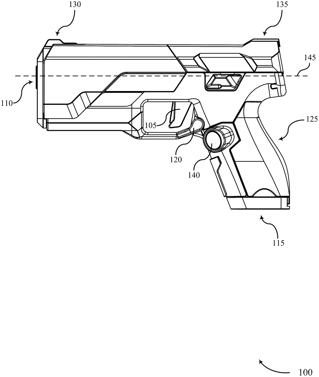
The present disclosure provides systems and techniques that can be implemented in a gun, such as an electromechanical gun. The gun may charge a capacitor bank, identify a trigger break based on an output generated by a trigger sensor, and transmit a signal based on the trigger break. Transmitting the signal may result in the capacitor bank discharging electric charge such that electric current is directed at an actuator mechanism so as to cause displacement of the actuator mechanism, and the displacement of the actuator mechanism may result in the propulsion of a projectile through a barrel of the gun. The gun may determine that a projectile has been fired based on an output of an accelerometer or a gyroscope, and the gun may recharge the capacitor bank in response to determining that the projectile has been fired.
Jun 23, 2026
A smart piston for a countermeasure expendable. The smart piston may include a main body, a gasket that operably engages with the main body, and an electronic system that is carried by the main body. Upon assembly, the electronic system of the smart piston is positioned between the main body and the gasket. The electronic system of the smart piston is configured to provide electrical communication to a payload of countermeasure expendable by passing the electrical communication through the main body to the payload of the countermeasure expendable where the electronic system and the payload are spaced apart from one another.
Jun 23, 2026
The present disclosure provides systems and techniques for an attachment that can be fastened to a gun. The attachment may include a top surface having a longitudinal axis and an aiming sight that is parallel with the longitudinal axis, a front surface having a latitudinal axis that is perpendicular to the longitudinal axis, the front surface including a muzzle aperture, a left surface, a right surface, and a fastening system. The fastening system may include a first mounting aperture of the left surface, a second mounting aperture of the right surface, and a locking pin capable of being positioned in the first mounting aperture and in the second mounting aperture such that the locking pin fastens the attachment to the gun. The attachment may be fastened to the gun such that the longitudinal axis is parallel with a longitudinal bore axis of the gun.
Jun 23, 2026
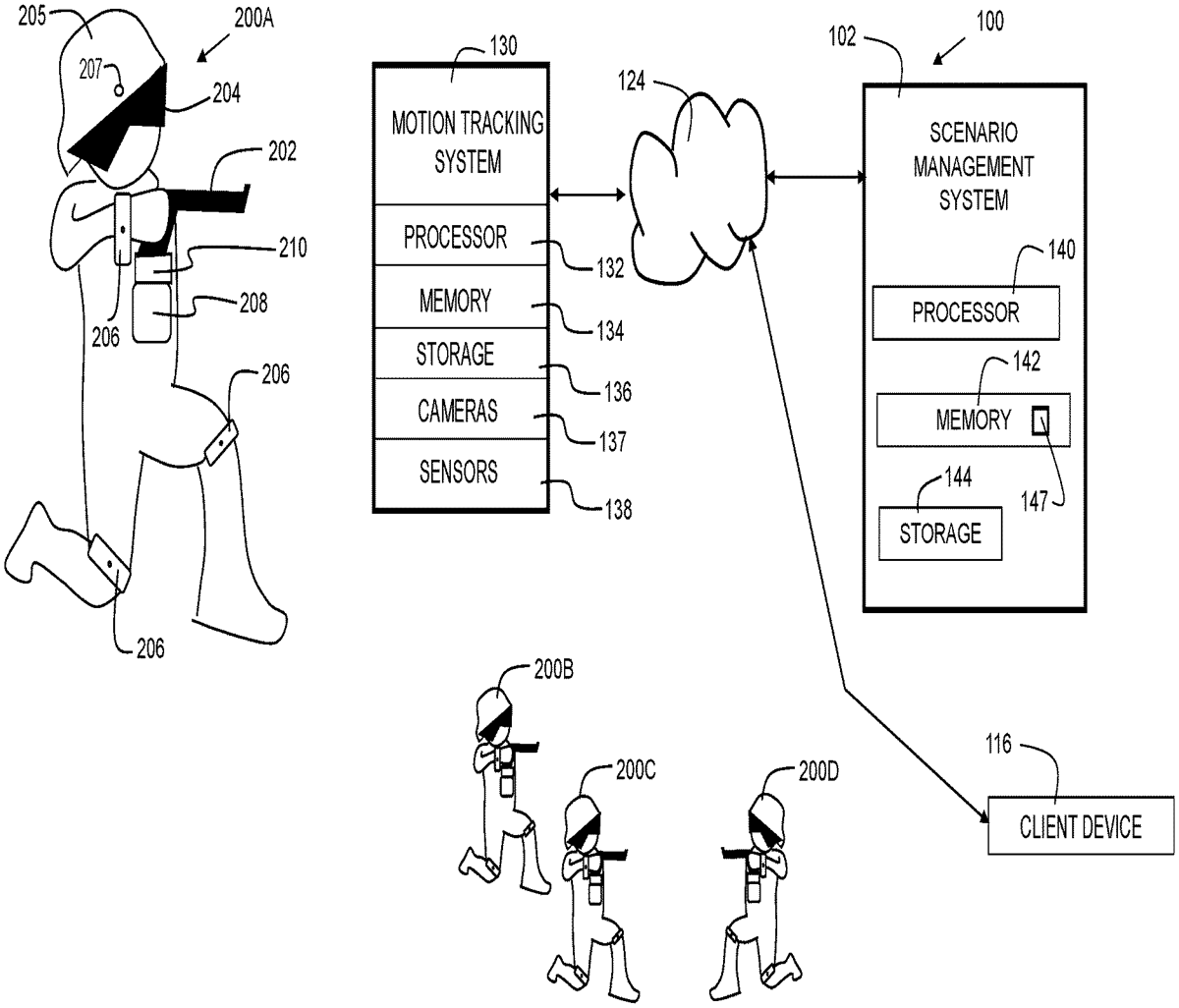
Disclosed embodiments provide systems and methods for simulation of firearm discharge and training of armed forces and/or law enforcement personnel. A motion tracking system tracks motion of one or more users. In embodiments, the users wear one or more sensors on their bodies to allow tracking by the motion tracking system. A scenario management system utilizes position, orientation, and motion information provided by the motion tracking system to evaluate user performance during a scenario. A weapon simulator includes sensors that indicate position of the weapon and/or orientation of the weapon. The weapon simulator may further provide trigger activation indications to the scenario management system. In embodiments, the scenario management system generates, plays, reviews, and/or evaluates simulations. The evaluation can include scoring based on reaction times, posture, body position, body orientation, and/or other attributes.
Jun 23, 2026
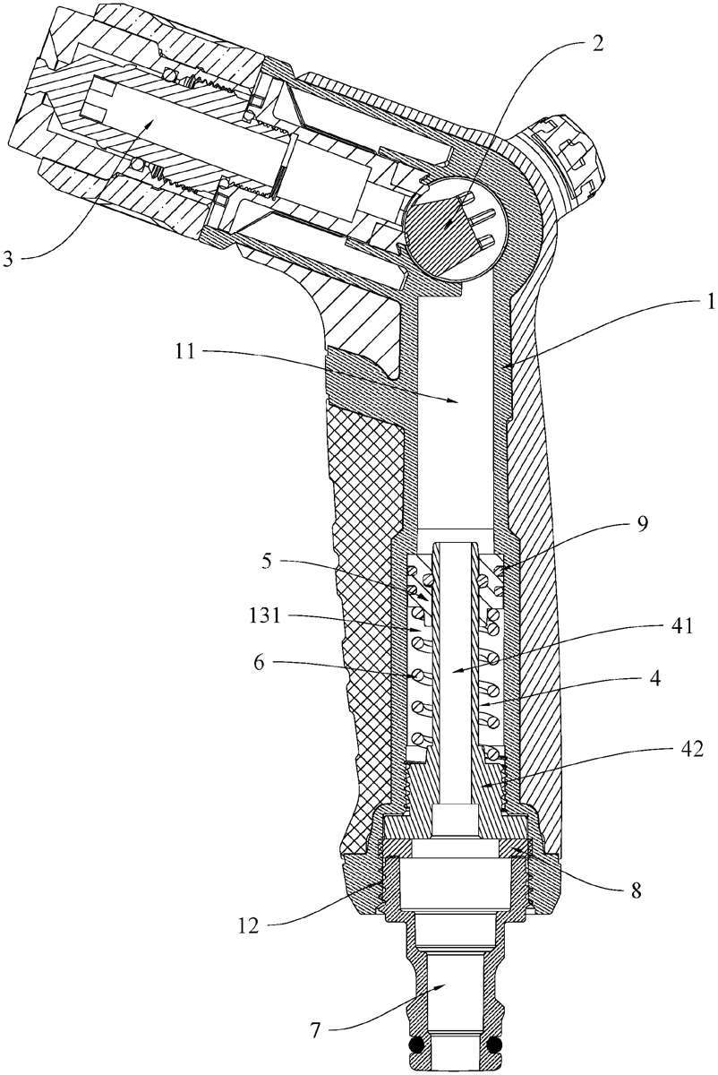
An anti-freeze water gun structure has a gun body. The gun body has a water passageway therein, a water inlet at a lower end thereof, and a water chamber between the water passageway and the water inlet. A guide tube is provided in the water chamber. A slidable piston is fitted onto the guide tube. A lower end of the guide tube has a sealing structure for blocking a lower end of the water chamber. A lower half of the water chamber, located below the piston, is surrounded by the piston, an inner wall of the water chamber, an outer wall of the guide tube and the sealing structure to form a closed chamber. An elastic member is provided in the closed chamber for elastically pushing the piston upward. A water channel communicating with the water inlet and the water passageway is formed in the guide tube.
Jun 23, 2026
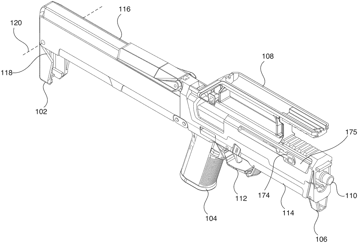
The present disclosure describes a foldable firearm that collapses into a folded state under spring pressure. The foldable firearm may include a foldable grip assembly. The foldable grip assembly may include a foldable pistol grip, a foldable trigger assembly, a folding bar, and a foldable hand stop. The foldable grip assembly may fold into the top shell of the foldable firearm. The foldable firearm may also include an ambidextrous charging handle assembly that may include a bottom portion, a top portion, a guide bar, and two opposing charging handles. The charging handles may be pulled to unfold the foldable firearm, and/or butterflied such that pivoting one charging handle causes the other charging handle to pivot. The first-pivoted charging handle may then be pulled rearwards to unfold the firearm. The first-pivoted charging handle may then be pulled further rearwards to rack the slide of the foldable firearm.
Jun 23, 2026
A protective carrying case for an object is disclosed, wherein the protective carrying case includes a top component, a bottom component, and semi-hexagonal ends, wherein the top component and the bottom component are constructed from carbon fiber. The protective carrying case additionally includes a retaining element with vacuum split functionality to retain elements within the case.
Jun 23, 2026
An adjustment turret for a riflescope has a base socket for mounting on the riflescope; and an adjusting ring which is rotatable about an axis of rotation relative to the base socket in a first rotation direction and in an opposite second rotation direction. An actuation element arranged between the adjusting ring and the base socket is adjustable from a first position to a second position by the rotation of the adjusting ring in the first rotation direction, and is adjustable from the second position to the first position in case of rotation of the adjusting ring in the second rotation direction. By the actuation element, in its first position, a first end stop for the rotation in the second rotation direction is formed, and, in its second position, a second end stop for the rotation in the first rotation direction is formed.
Jun 23, 2026
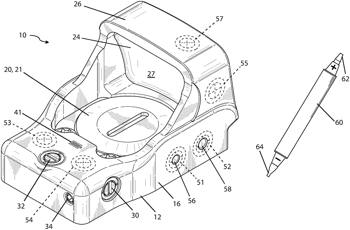
An weapon sight system includes a weapon sight having body with an optical element that is configured to superimpose a reticle that is visible through the optical element. The weapon sight includes a controller in electronic communication with and configured to control a light source. The light source may include an LED for generating a reticle image on the optical element at a plurality of different brightness conditions. The light source may include an array of LEDs for generating multiple different reticle images on the optical element. The weapon sight includes a Hall effect sensor in electronic communication with the controller to adjust user-selectable settings including reticle brightness or reticle image. The weapon sight system includes a magnetic input device for providing an input to the Hall effect sensor of the weapon sight.
Jun 23, 2026
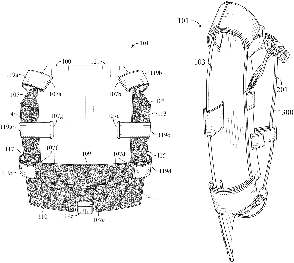
A modular body harness is disclosed, including a sheet including a plurality of slots. A first set of hook and loop strips are positioned horizontally at a bottom portion of the sheet and a second set of hook and loop strips are positioned vertically above the first set of hook and loop strips. A plurality of self-gripping hook and loop strips are each engaged with one of the plurality of slots and attached to themselves. A parachute cord extends through a portion of the plurality of self-gripping hook and loop strips.
Jun 23, 2026
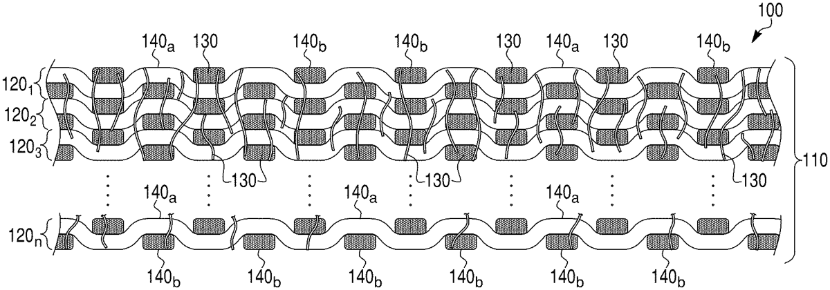
A consolidated material and method for forming a consolidated material. The consolidated material comprises a plurality of woven fabric layers that are mechanically entangled together. The plurality of woven fabric layers comprise fibers. The plurality of woven fabric layers are mechanically entangled together with fibers of the plurality of woven fabric layers and without nonwoven fibers. At least some fibers of the plurality of woven fabric layers extend in the Z-direction perpendicular to the x-y plane of the plurality of woven fabric layers. Methods for forming a consolidated material are also provided.
Jun 23, 2026
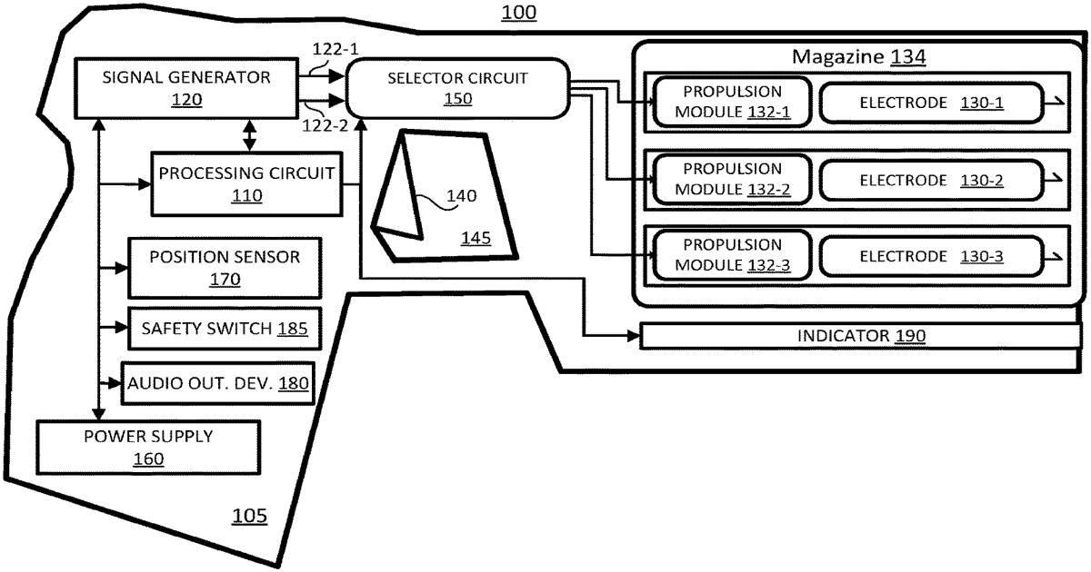
An indication may be automatically provided based on a position of a weapon. The weapon may comprise a conducted electrical weapon (“CEW”). The indication may be provided from an indicator integrated with the weapon. The indication may comprise light emitted from a laser indicator integrated with the weapon. The indicator may be selectively activated in accordance with the position to provide the indication. The indication may be provided when the weapon is oriented in a direction in which a projectile may be deployed toward a remote location. The indication may be automatically provided when the weapon is disposed in a horizontal direction or a range of angles of the CEW. Methods, systems, and devices may selectively provide the indication in accordance with the position.
Jun 23, 2026
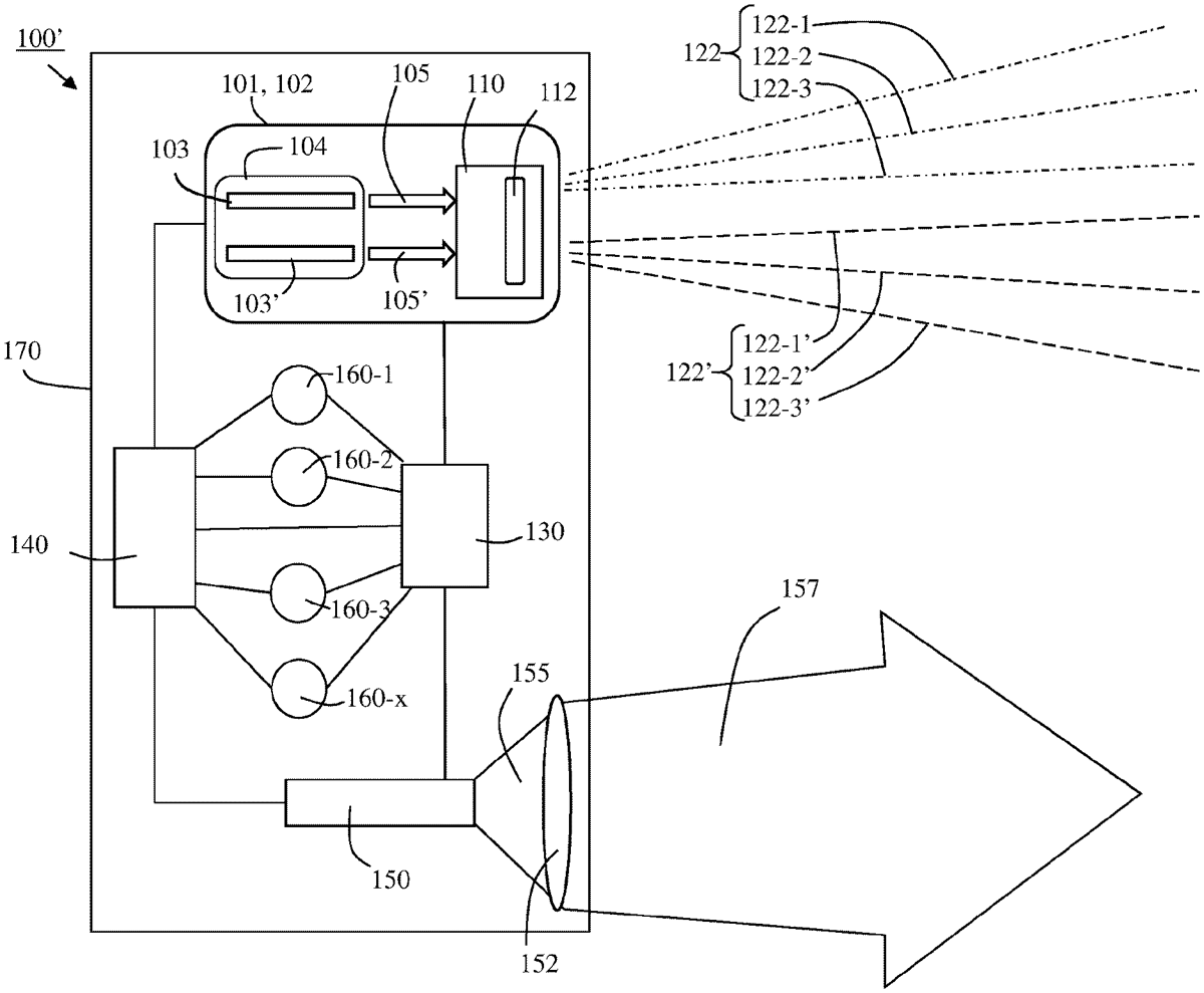
A multifunction portable illumination system includes a housing having a power source. A broadband illumination source connected to the power source and capable of producing broadband illuminating light. The system includes an imaging disruption assembly including at least one narrow-band light source capable of generating one or more high intensity light beams (HILB) and a light modifying assembly configured to modify the one or more HILB to produce a Modified HILB. At least one Modified HILB may have the requisite irradiance to cause disruption of an imaging system.
Jun 23, 2026
A device is configured for braking and recovering projectiles and includes a support from which several braking tubes are suspended. The braking tubes are suspended by one of their ends on the support. The device further includes a motor driving the support in rotation about an axis of rotation. The braking tubes are suspended from the support by gravity so as to absorb the energy of a projectile impacting one or more of the several braking tubes.
Jun 23, 2026
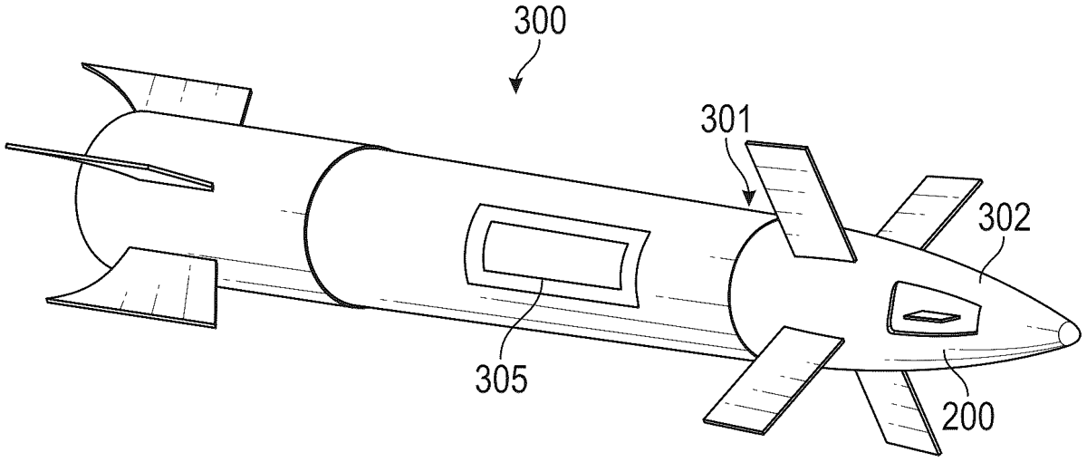
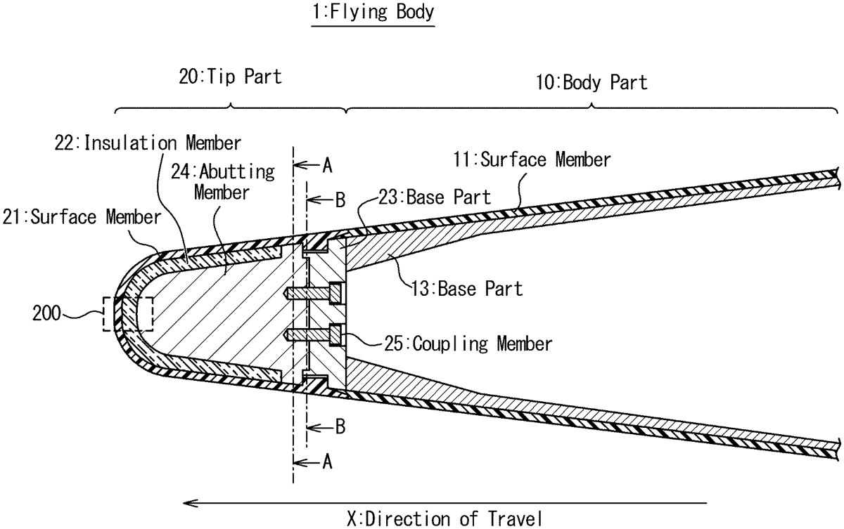
A heat resistant structure is applied to a flying body having a tip part and a body part. The tip part is arranged in a front end of the flying body with respect to a direction of travel of the flying body. The body part is arranged behind the tip part with respect to the direction of travel. The tip part is provided with a surface member, a base part, and an insulation member. The surface member is arranged on an outer surface of the tip part and has a melting point higher than a maximal temperature reached on a surface of the flying body when the flying body moves in an atmosphere and is heated. The base part couples the surface member to the body part. The insulation member is arranged between the surface member and the base part, and thermally insulates the base part from the surface member.
Jun 23, 2026
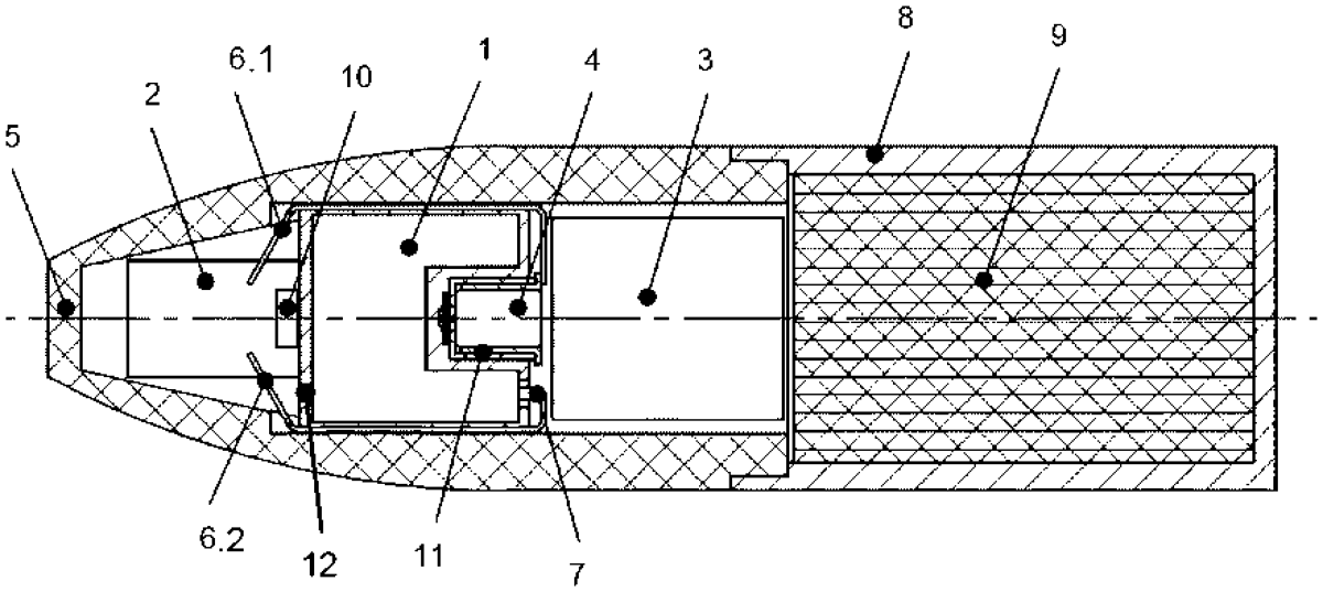
The invention relates to an ignition device for ammunition, in particular medium-caliber ammunition, comprising at least one battery and at least one electric or electronic ignition-chain component, wherein: the battery has a battery housing; an electrolyte and at least two electrodes are located in the battery housing; an explosive charge of the ammunition can be caused to explode by means of the electric or electronic ignition-chain component, and the energy required to trigger the electric or electronic ignition-chain component can be provided by means of the battery. The ignition device provides for a sufficient amount of energy, and the volume in the ignition device is at the same time utilized particularly efficiently in that the battery housing has a cup-shaped recess, and at least part of the at least one electric or electronic ignition-chain component is located in the cup-shaped recess.
Jun 23, 2026
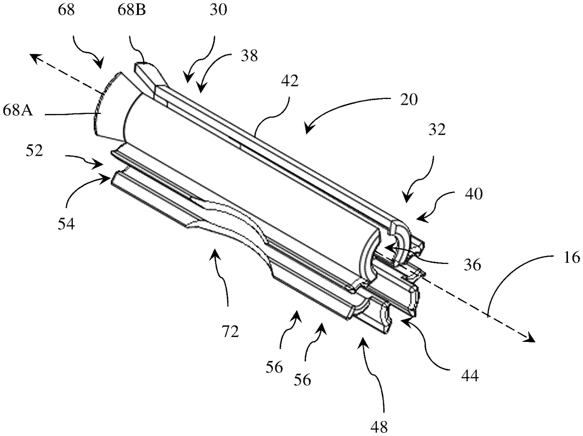
A connector for use with detonation device(s) associated with an explosive detonation system is provided. The connector includes a body, a lower channel, a first side channel, and a second side channel. The body has a first end and a second and is centered on an axis. The first end and the second end are positioned along the axis. The body defining a main channel with a first main end and a second main end. The body main, lower, first side and second side channels are configured to receive first, second, third and fourth detonation device, respectively.
Jun 23, 2026
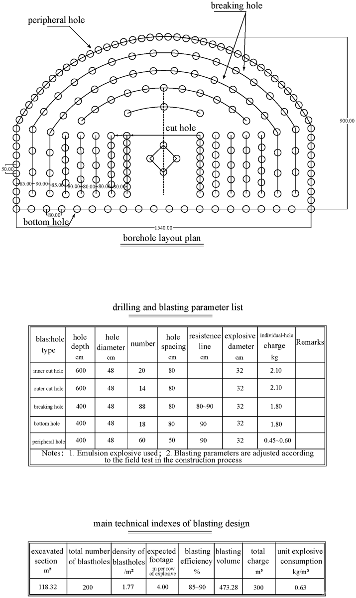
The invention provides a method for evaluating deep-buried tunnel blasting parameters, and belongs to the technical field of mine engineering. The method comprises: setting multiple diverse blasting schemes; selecting a plurality of test sections with the same geological characteristics, the number of the test sections corresponding to the number of the blasting schemes; blasting the test sections using the blasting schemes, and obtaining diversified monitoring data of each test section; and comparing the diversified monitoring data to select the optimal blasting schemes for the test sections. According to the method for evaluating the deep-buried tunnel blasting parameters, by implementing different blasting schemes in test sections with the same geological characteristics, diversified monitoring data of the test sections are obtained and compared to select the optimal blasting schemes for the test sections, so as to ensure the safety and quality of blasting excavation of deep-buried tunnels.
Jun 23, 2026
Jun 23, 2026
Jun 23, 2026
Jun 9, 2026
A battery system for a heavy-duty vehicle, comprising at least one battery section which comprises a plurality of traction battery packs, a hold-and-release mechanism for connecting the battery section to the vehicle at a first point of connection and for enabling quick-release of the battery section from the vehicle in case of emergency, a towing attachment element connected to the battery section and presenting a second point of connection for receiving a towing device for transporting the battery section away from the vehicle by towing, after the hold-and-release mechanism has released the battery section from the vehicle, wherein the first point of connection is different from the second point of connection. The invention also relates to a heavy-duty vehicle comprising such a battery system.
Jun 9, 2026
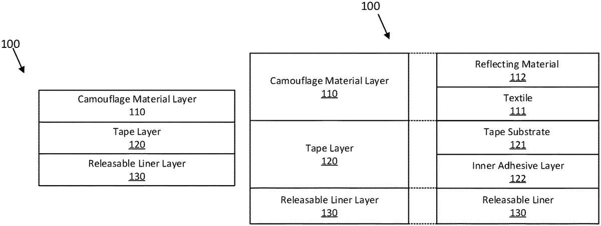
The present disclosure relates to a multispectral camouflage tape for temporary multispectral camouflage of objects, such as weapons or military, comprising a camouflage material layer having camouflage properties in the visual and thermal infrared wavelength regions, the camouflage material layer including a textile and a thermal-radiation reflecting material; a tape layer including a tape substrate having an inward-facing side coated with an inner adhesive layer; and a releasable liner layer releasably adhered to the inward-facing side of the tape substrate through the inner adhesive layer, wherein the camouflage material layer is adhered to the tape substrate such that the camouflage material layer and the tape layer form a tape configured to adhered to an object by the inner adhesive layer at an inward-facing side of the tape substrate.
Jun 9, 2026
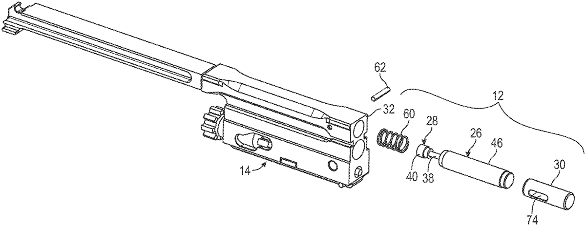
A firearm with buffer assembly has a frame, a bolt assembly operable to reciprocate with respect to the frame between a forward battery position and a rearward recoil position, and the bolt assembly including a hydraulic damper assembly. The hydraulic damper assembly may include at least a first portion connected to the bolt assembly. The first portion of the hydraulic damper assembly may be fixed to the bolt assembly such that the first portion does not move with respect to the bolt assembly in response to forces applied in the forward and rearward direction. The entire hydraulic damper assembly may reciprocate with the bolt assembly. The hydraulic damper assembly is operable to provide damping in response to the bolt assembly striking the frame upon reaching the forward battery position and in response to the bolt assembly striking the frame upon reaching the rearward recoil position.
Jun 9, 2026
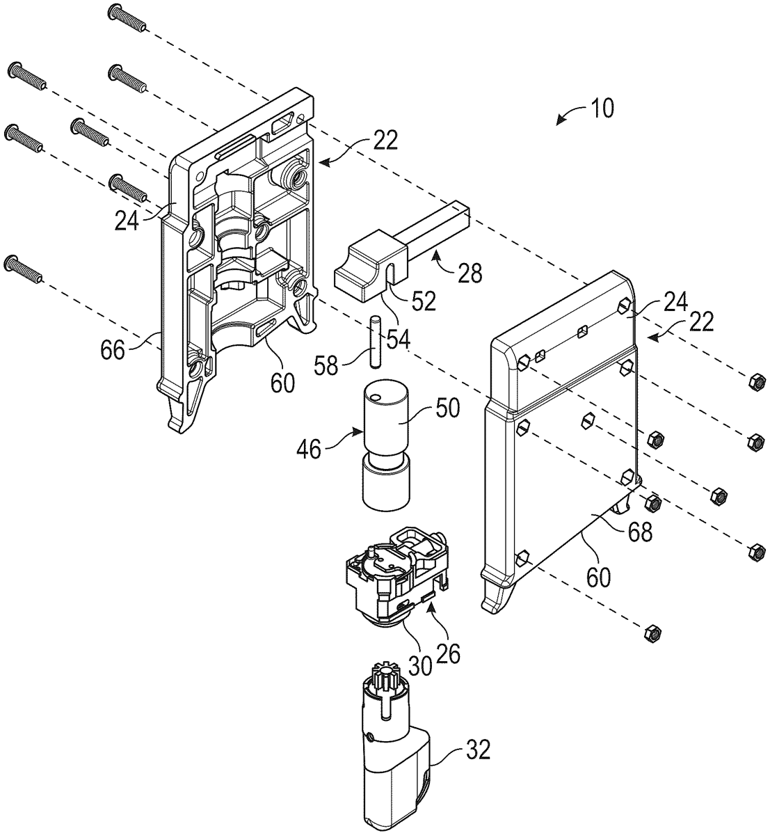
Locks for a firearm have a lock body configured to be closely and removably received in the magazine well, the lock body having an upper portion configured to extend into the bolt passage when installed in the firearm, with the upper portion interposed between the reciprocating bolt and the forward extending barrel, a locking mechanism at a lower portion of the lock body and having a locked condition and an unlocked condition, and a latch element connected at the upper portion of the lock body and interfacing the locking mechanism to move between an unlocked position when the locking mechanism is in the unlocked condition and a locked position when the locking mechanism is in the locked condition. The latch element may protrude from the lock body when in the locked position. The latch element may protrude in a forward direction from the lock body when in the locked position.
Jun 9, 2026
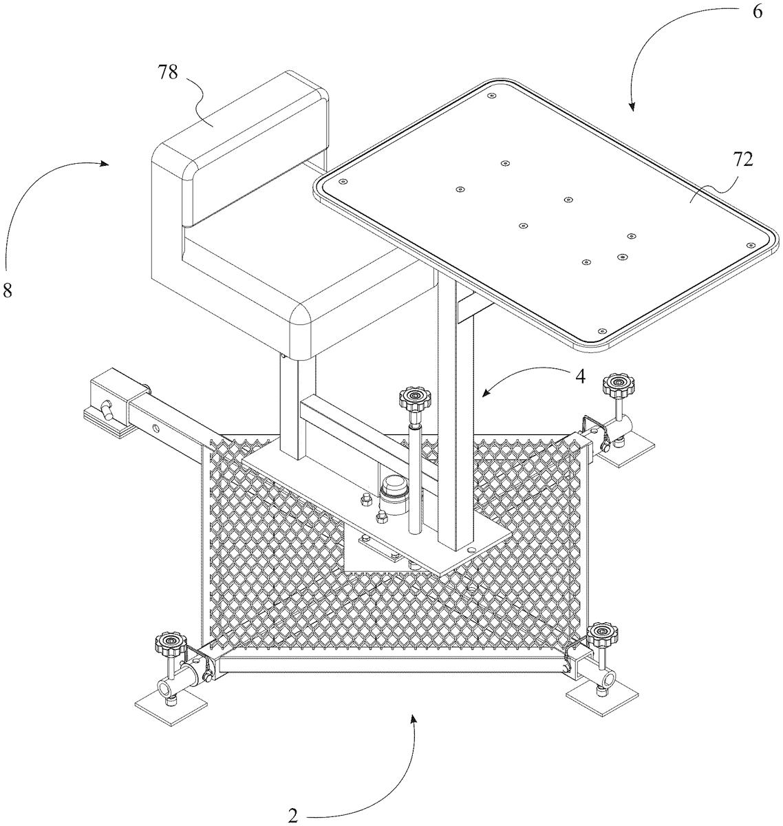
A shooting bench is an adaptable device for a firearm, that is designed to be used with a receiver hitch on a vehicle such as a truck or UTV. The device has two trailer jacks used for support and level adjustment which makes the bench very stable and ideal for long range shooting. Further, the device can be used on the ground with a leveling kit for stability and mounted to an elevated hunting blind. Furthermore, the device can rotate 360 degrees and is adjustable with a hand brake that can be operated while seated, locking the bench at any angle. The adjustable seat can extend upwards up to 8 inches and is designed to engage with supporting elements and structures such as bipods, sandbags, “lead sleds” and similar devices. Thus, the device is a hitch receiver mounted shooting bench with high portability that secures to an external vehicle.
Jun 9, 2026
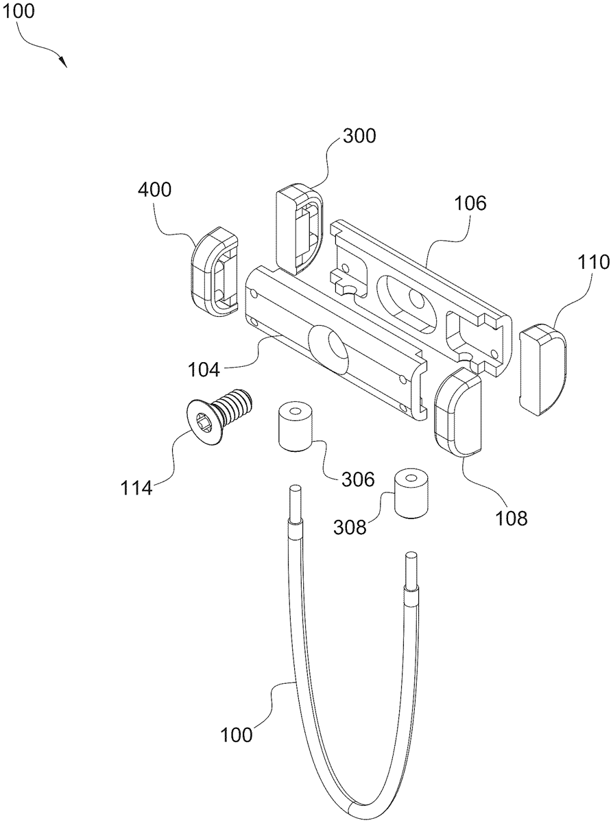
A firearm accessory connector includes a mount assembly having a first side and a second side to secure together via one or more fasteners; a flexible member extending from a first end to a second end, the flexible member secured to the mount assembly such that a loop is formed by the flexible member; the flexible member and the mount assembly are to secure an accessory to a firearm.
Jun 9, 2026
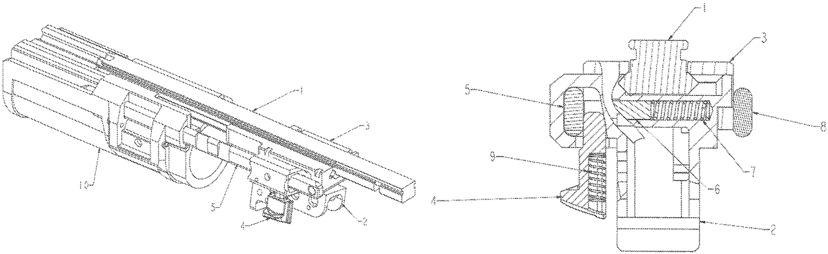
A grenade launcher, comprising a barrel ( 10 ), a trigger mechanism base ( 3 ) and a breech ( 2 ) wherein the trigger mechanism base ( 3 ) is adapted to be mounted on a host rail interface ( 1 ). On the opposed sides ( 3 ) of the trigger mechanism base ( 3 ), guide rails ( 5, 8 ) are arranged for sliding mounting of the barrel ( 10 ). The host rail interface ( 1 ) is clamped between the breech ( 2 ) and the trigger mechanism base ( 3 ). The breech ( 2 ) is fitted with a cavity ( 11 ) that surrounds one of the guide rails ( 5 ). The inner wall of the cavity ( 11 ) is pressed to this guide rail ( 5 ) by a detent ( 4 ) that is insertable between this guide rail ( 5 ) and the opposed inner wall of the cavity ( 11 ) that is inclined in a wedge-like way. A pin ( 6 ) bears on this guide rail ( 5 ) from the inner side, the pin being mounted in a sliding way in a recess transversally in the breech ( 2 ) and fitted with a compression spring ( 7 ).
Jun 9, 2026
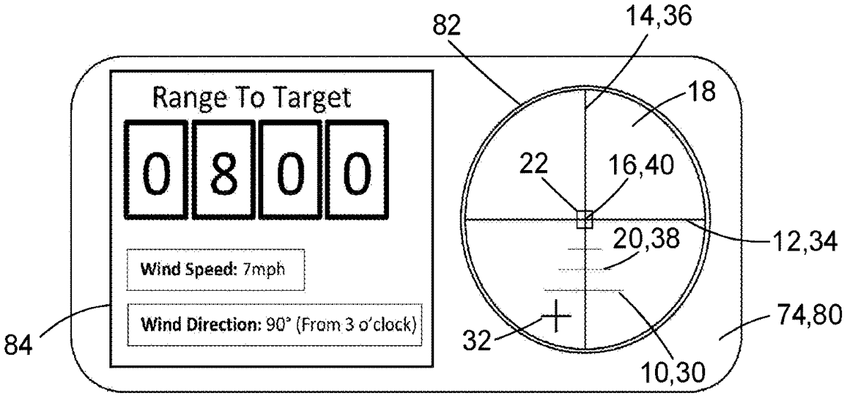
A method of adding digital functionality to a scope. A scope reticle from the scope is aligned with a virtual reticle from a digital overlay of an electronic display device coupled to the scope. The scope reticle is present in a first coordinate space of the scope image and the virtual reticle is present in a second coordinate space. The alignment of the reticles maps the first coordinate space to the second coordinate space. The coordinate spaces are then locked and the virtual reticle is made invisible, switching from a configure mode to an operate mode. Digital functionality can then be provided to the scope via the digital overlay. This may include an aiming indicator which works with the scope reticle.
Jun 9, 2026
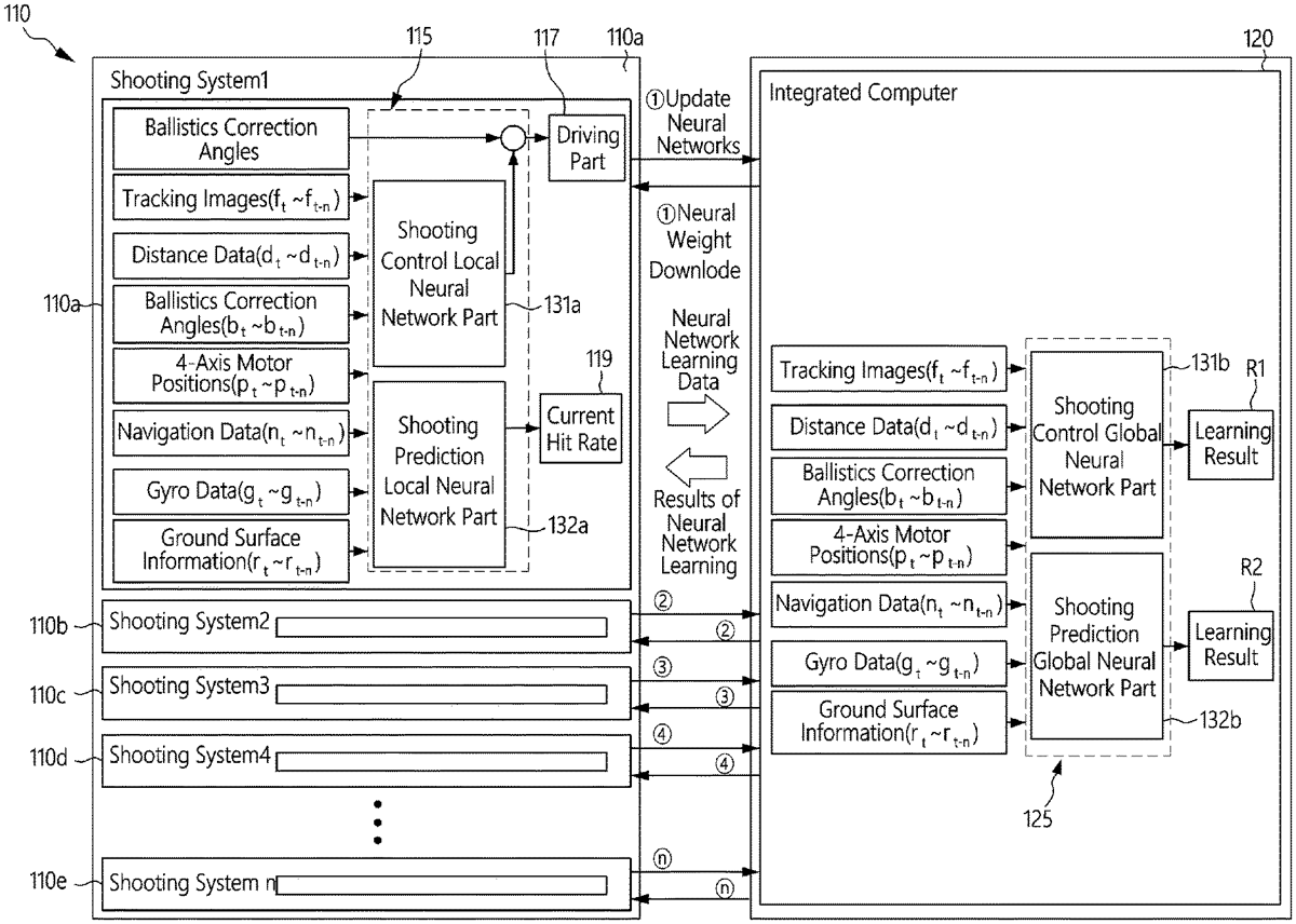
A system includes a shooting system comprising at least one first processor configured to: receive shooting ballistics-related data and shooting result data in real time; and detect real-time surrounding data; and an integrated computer comprising at least one second processor configured to: receive the shooting ballistics-related data and the shooting result data from the shooting system; derive learning result data based on the shooting ballistics-related data and the shooting result data; and transmit the learning result data to the shooting system.
Jun 9, 2026
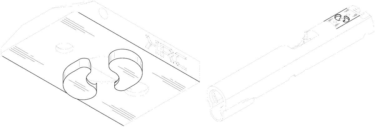
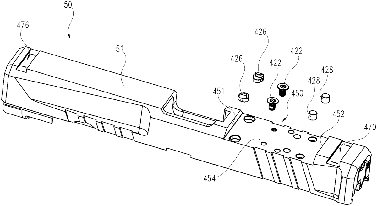
A slide for a firearm includes a top surface and an optical sight mounting surface recessed into the top surface of the slide. At least one pin opening is defined through a portion of the optical sight mounting surface and is configured to receive a pin for attaching an optical sight to the slide. At least one sight attachment opening is defined through the optical sight mounting surface to serve as another connection point for the optical sight. The pin opening and the sight attachment opening allow the optical sight to be attached directly to the slide of the firearm.
Jun 9, 2026
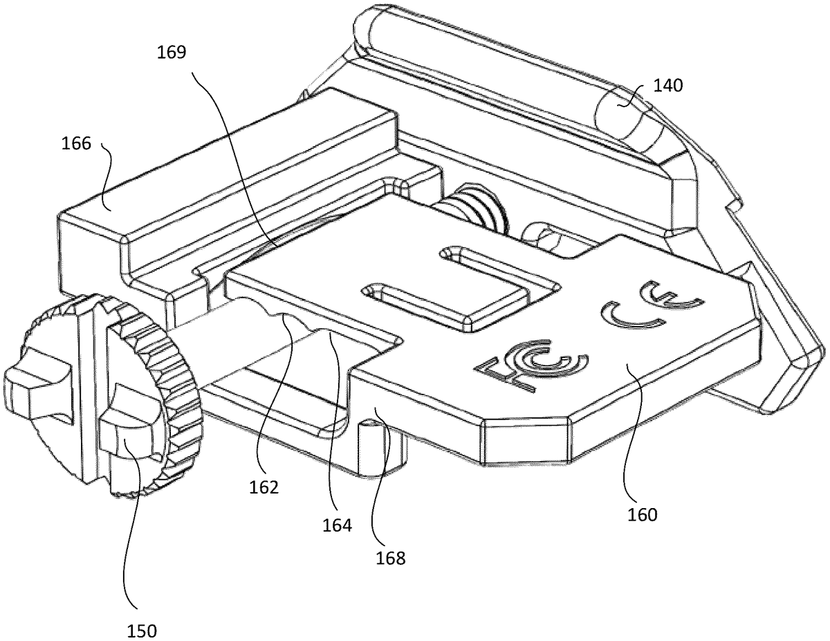
A firearm accessory mounted to a firearm accessory rail and allowing adjustment of the accessory relative to the firearm accessory rail includes an indexing member having a tab structured to engage with one of the series of slots of the firearm accessory rail, and having two or more indexing slots, the two or more indexing slots spaced apart from one another at a distance less than the regular pitch interval of the accessory rail, and a single clamp having a crossmember structured to engage with one of the two or more indexing slots, the single clamp structured to simultaneously secure the accessory and the indexing member to the firearm accessory rail in a single clamping action.
Jun 9, 2026
An assembly ( 7 ) for triggering an explosive in a hole ( 9 ) to produce an explosive blast in the hole includes (a) an explosion trigger ( 15, 19 ) for triggering the explosive in the hole, (b) a detonation unit body ( 21 ) that is configured to be located at or proximate an open end of the hole in an initial position of the assembly in the hole and (c) a trigger cord ( 31 ) that is connected to the detonation unit body and to the explosion trigger.
Jun 9, 2026
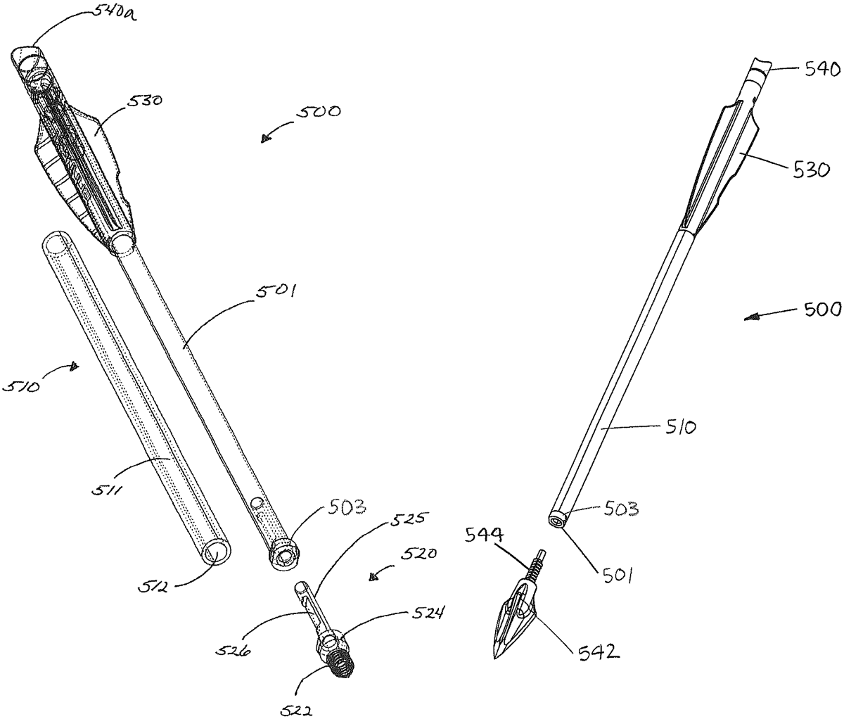
A molded arrow assembly preferably includes an insert and an outsert for an arrow or an insert/outsert assembly. The molded arrow assembly may include an insert having a cylindrical body with a first end and a second end. The second end may be dimensioned to fit within a bore of an arrow shaft. The first end may terminate in a prong containing male threads. The insert/outsert assembly may also include an outsert having a cylindrical wall with an arrow shaft end and an arrowhead end. The cylindrical wall may also include a center bore extending between the arrow shaft end and the arrowhead end. The center bore may contain a threaded region containing female threads. The threaded region may be located intermediate of the arrowhead end and the arrow shaft end and may extend between a top shoulder and a bottom shoulder.
Jun 9, 2026
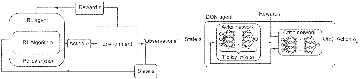
A computer-implemented method of training a machine learning, ML algorithm to control spin-stabilized steerable projectiles is described. The method comprises: obtaining training data including respective policies and corresponding trajectories of a set of spin-stabilized steerable projectiles including a first projectile, wherein each policy relates to steering a projectile of the set thereof towards a target and wherein each corresponding trajectory comprises a series of states in a state space of the projectile (S 2001 ); and training the ML algorithm comprising determining relationships between the respective policies and corresponding trajectories of the projectiles of the set thereof based on respective results of comparing the trajectories and the targets (S 2002 ).
Jun 9, 2026
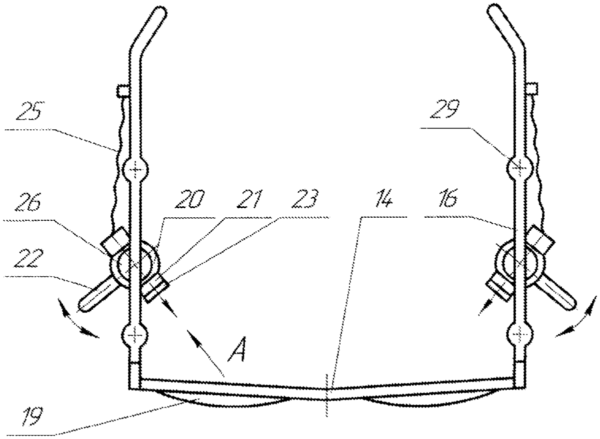
Aiming glasses can be used for finding a line of aim when shooting firearms and pneumatic weapons, as well as in archery, billiards, golf, and curling. The aiming glasses include an optical part in which aiming guides can be moved and rotated relative to a frame in order to align the center of the guides with the visual axis of the eye, which passes through the center of the fovea and the target, and to vertically orient the guides. The results are improved at aiming accuracy and greater versatility of the aiming glasses for use in different types of sport. A further technical result is that of enabling a sportsperson to cultivate a reproducible afterimage of the aiming guides at the start of a line of aim.
Jun 9, 2026
Jun 9, 2026
Jun 2, 2026
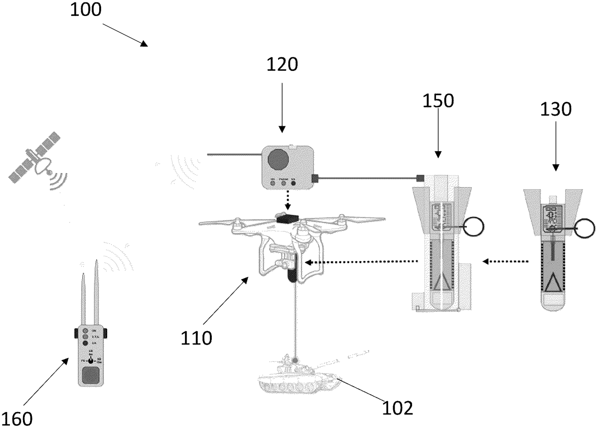
A system for delivering ordinance is disclosed. The system includes a flight capable drone having a lift capacity suitable for carrying a munition, a fire control module in communication with the munition, and a handheld device in remote communication with the fire control module. At least one encrypted firing code generated by the fire control module is received by the handheld device and the munition is armed in accordance with at least the location of the drone.
Jun 2, 2026
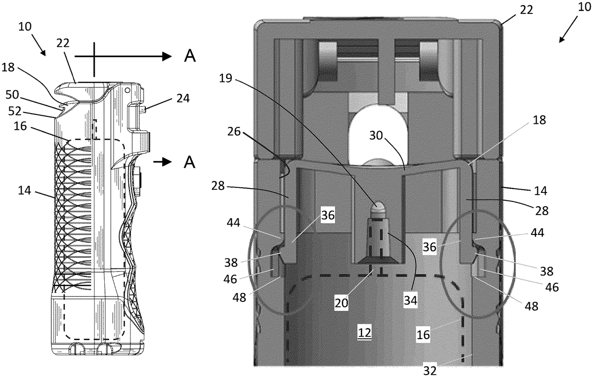
Dispensers for spraying a chemical irritant and methods of using dispensers. Such a dispenser includes a casing having an interior cavity and an access opening to the cavity. The interior cavity receives a cannister with a release valve oriented toward the access opening. An actuator is slidingly disposed in the access opening for actuating the release valve, and a retention mechanism releasably retains the actuator in the access opening. The retention mechanism includes a resilient leg and a radial shoulder extending radially inward from an interior wall of the interior cavity. The radial shoulder captures a foot of the resilient leg so as to inhibit removal of the actuator from the access opening. A wall of the actuator is operable to deflect the resilient leg radially inward to enable the foot to travel over and past the radial shoulder and allow the actuator to be removed through the access opening.
Jun 2, 2026
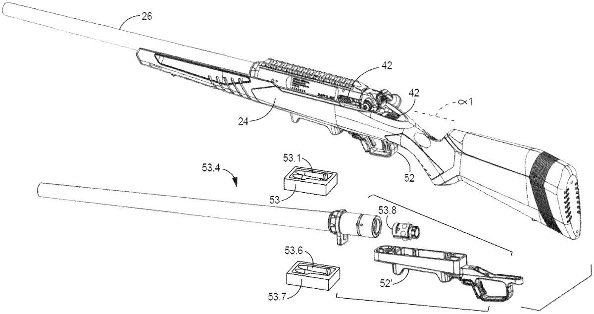
A rifle having a straight pull bolt assembly with a bolt handle that extends outward and downward from a bolt operation mechanism. The bolt handle rotatable a limited rotational range forward and rearwardly about a horizontal axis for operating the mechanism. The handle can be reconfigured to position its rotational range about the horizontal axis and can be attached to the mechanism at either left or right sides to provide for ambidextrous operation. Bolt heads, lower frame members with magazine wells, and barrel assemblies can be readily swapped to change ammunition. The bolt assembly can be unlocked by firing or by a thumb push button release at the backside of the mechanism. A bolt removal release mechanism is forward of the thumb pushbutton and an ejector includes a spring bias and cam follower surface to reliably eject casings.
Jun 2, 2026
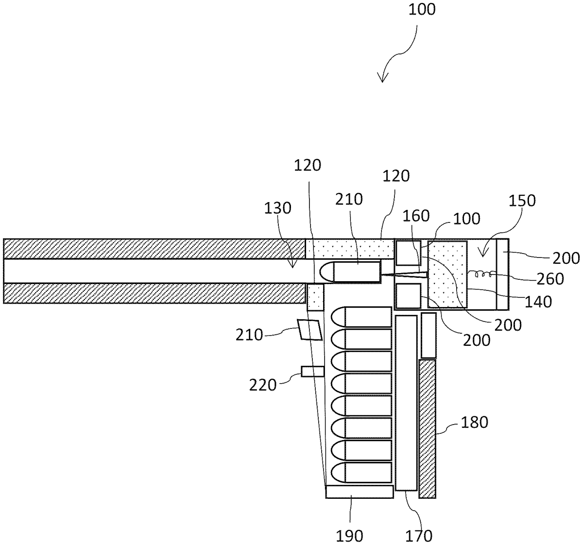
A firearm includes a fixed magnet and a movable magnet, wherein at least one of the fixed magnet and the movable magnet is an electromagnet. A control unit can charge the electromagnet causing the movable magnet to move towards the fixed magnet with high speed under electromagnetic forces. A firing pin is coupled with a movable magnet. The movable magnet moving at high speed causes the firing pin to strike a bullet loaded in the firearm resulting in the firing of the bullet.
Jun 2, 2026
A trigger reset device includes a trigger block with a front end and a rear end, a hooker and a link trigger pivoted to the trigger block, and a safety switch being displaceably switchable between an open position and a closed position, and further includes a linkage part, a button and a retractor. The button can be operated to allow the linkage part to displace upward, and the retractor can stop and position the linkage part, drive the link trigger to pivot the linkage part, and separate the hooker, in order to achieve a trigger reset function, which makes the operation more convenient and quicker, and also improves the operation efficiency, and the design is simple and easy to operate, which prolongs the service life of the product and reduces the costs of subsequent maintenance and replacement.
Jun 2, 2026
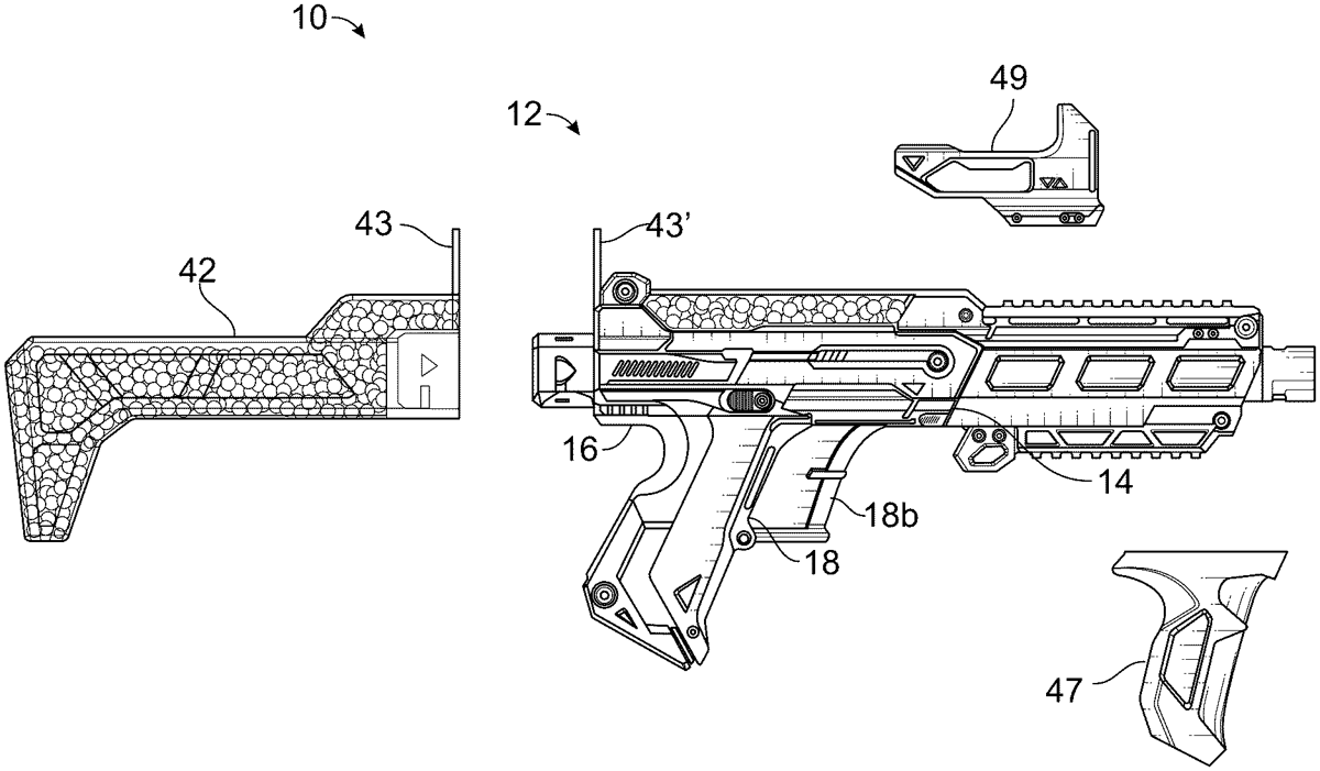
Launcher system with apparatus and methods for a toy projectile blaster removably interfaced with shoulder or butt stock receptacle hopper for multiple additional projectiles, user operable providing a hopper receptacle passageway in alignment with a firing projectile launching element to a projectile launching barrel for discharging projectiles. The pre-firing area allows projectile rounds to be received, while coupling the hopper stock projectiles magazine holds projectiles located distally along an upper portion of the pre-firing area for communication to outwardly launch the received projectile rounds. A user operable barrier at the hopper stock projectiles magazine receptacle opens and feeds by gravity into the pre-firing area The hopper stock projectiles magazine receptacle tilts towards the breech for feeding received projectile received into the pre-firing area.
Jun 2, 2026
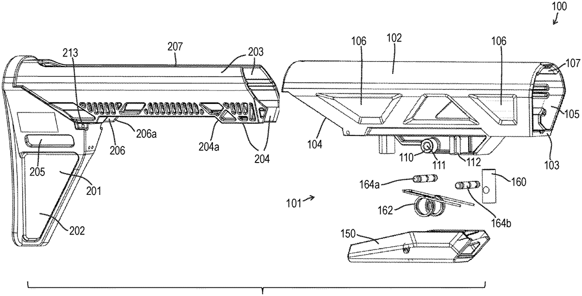
A buffer tube cover assembly includes a cover base assembly and an insert attached to a rear side of the cover base assembly. The cover base assembly includes a cover tube, a lever, a buffer locating portion, a spring, and at least one pin. The insert includes at least one forward protruding member disposed inside the cover base assembly.
Jun 2, 2026
A projectile launcher attachment adapted for a standard unmodified firearm receiver capable of launching a variety of projectiles including flare, smoke round, and gas and less lethal projectiles. The launcher attachment is easily installed having a barrel breach release for loading and unloading rounds using the existing firearm receiver magazine release and provides a single shot break down barrel configuration utilizing the existing firearm attachment pin as a pivot point. A unique firing pin and firing control mechanism is interengaged with the existing firearm trigger and firearm hammer for integral select operation.
Jun 2, 2026
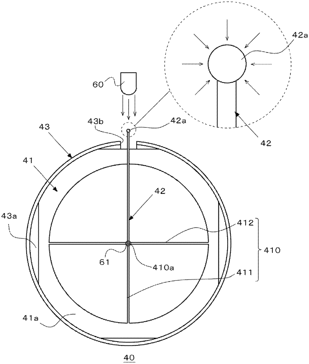
Provided is a reticle unit that includes a reticle with a sight line; an optical fiber that forms a dot by guiding light from a light source to a center of the sight line; and a frame to which the reticle is attached, wherein a light incident portion for receiving light is formed at one end of the optical fiber protruding out of a cutout portion of the frame, a light-emitting portion for emitting light is formed at another end of the optical fiber, the light incident portion has a spherical surface having a diameter greater than that of the optical fiber, the light-emitting portion has an inclined surface that reflects light passing through the optical fiber, and the optical fiber is fixed along a part of the sight line so that the light-emitting portion is positioned at the center of the sight line.
Jun 2, 2026
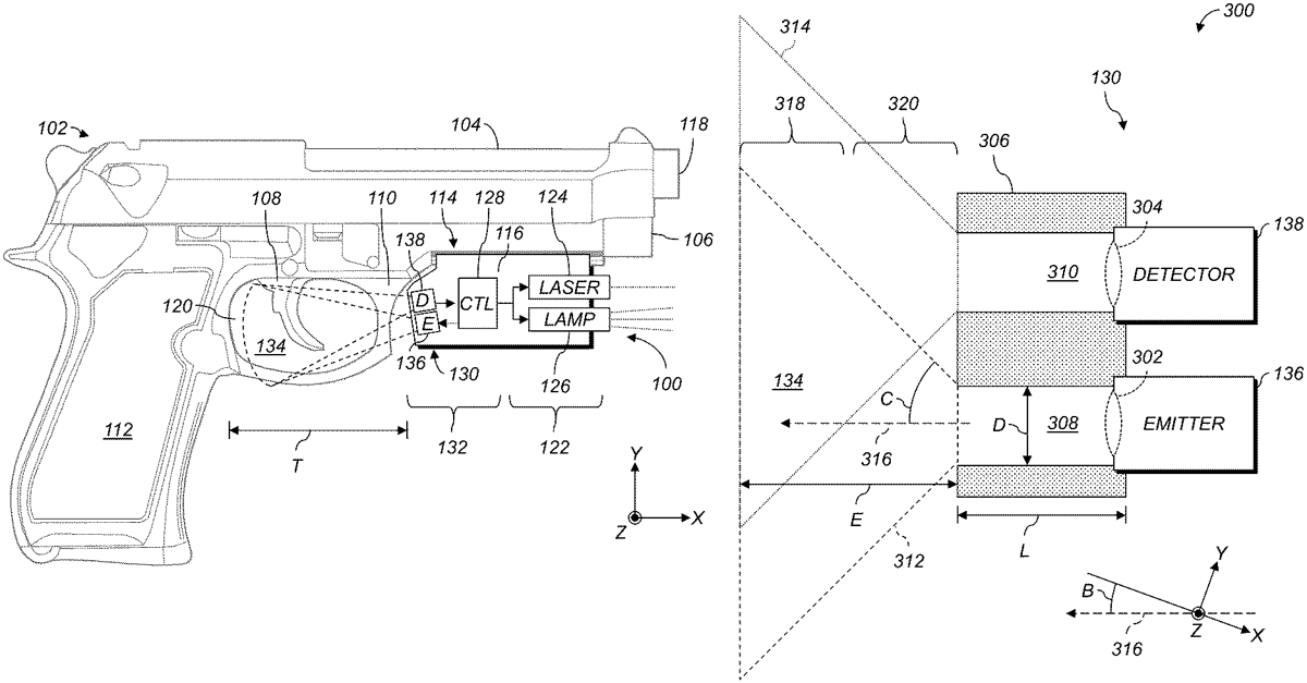
A kit includes a deterrent device, a grip activation system, and a housing supporting the grip activation system. The housing positions the grip activation system so that a sensing space of the grip activation system extends at least partly adjacent to a trigger guard of the deterrent device. The grip activation system includes an emitter configured to emit first electromagnetic radiation having a first wavelength; a detector configured to detect second electromagnetic radiation having the first wavelength; and a controller. The controller determines, based at least in part on the second electromagnetic radiation, that an object is present in the sensing space; and provides an activation signal to an activatable system in response to determining that the object is present in the sensing space. The activatable system can include a light source. Some examples include a housing, a grip activation system, and an activatable system.
Jun 2, 2026
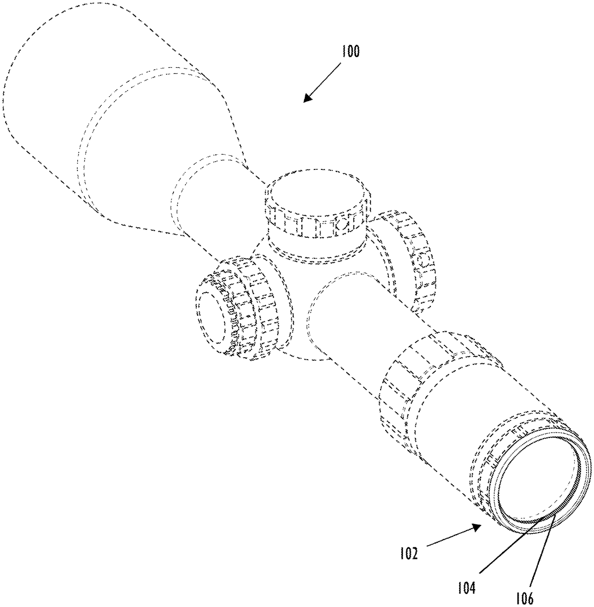
Disclosed herein are alignment features for scopes, such as alignment rings for telescopic sights. For example, a scope can includes a proximal end having an interior surface. The proximal end is that which a user aligns his or her eye in order to visualize a target. The scope may also include an alignment ring on the interior surface of the proximal end. The alignment ring assists a user in determining whether his or her eye is properly aligned with a longitudinal axis of the scope. With correct eye alignment, the alignment ring is not visible. With incorrect eye alignment, at least a portion of the alignment ring is visible, thus ensuring accurate sighting.