US12644663 - Trigger reset device
The trigger reset device features a trigger block with a safety switch, a linkage part, and a button that facilitates the upward movement of the linkage part to enhance trigger operation efficiency. This design simplifies the trigger reset process, prolongs the device’s service life, and reduces maintenance costs.
Claim 1
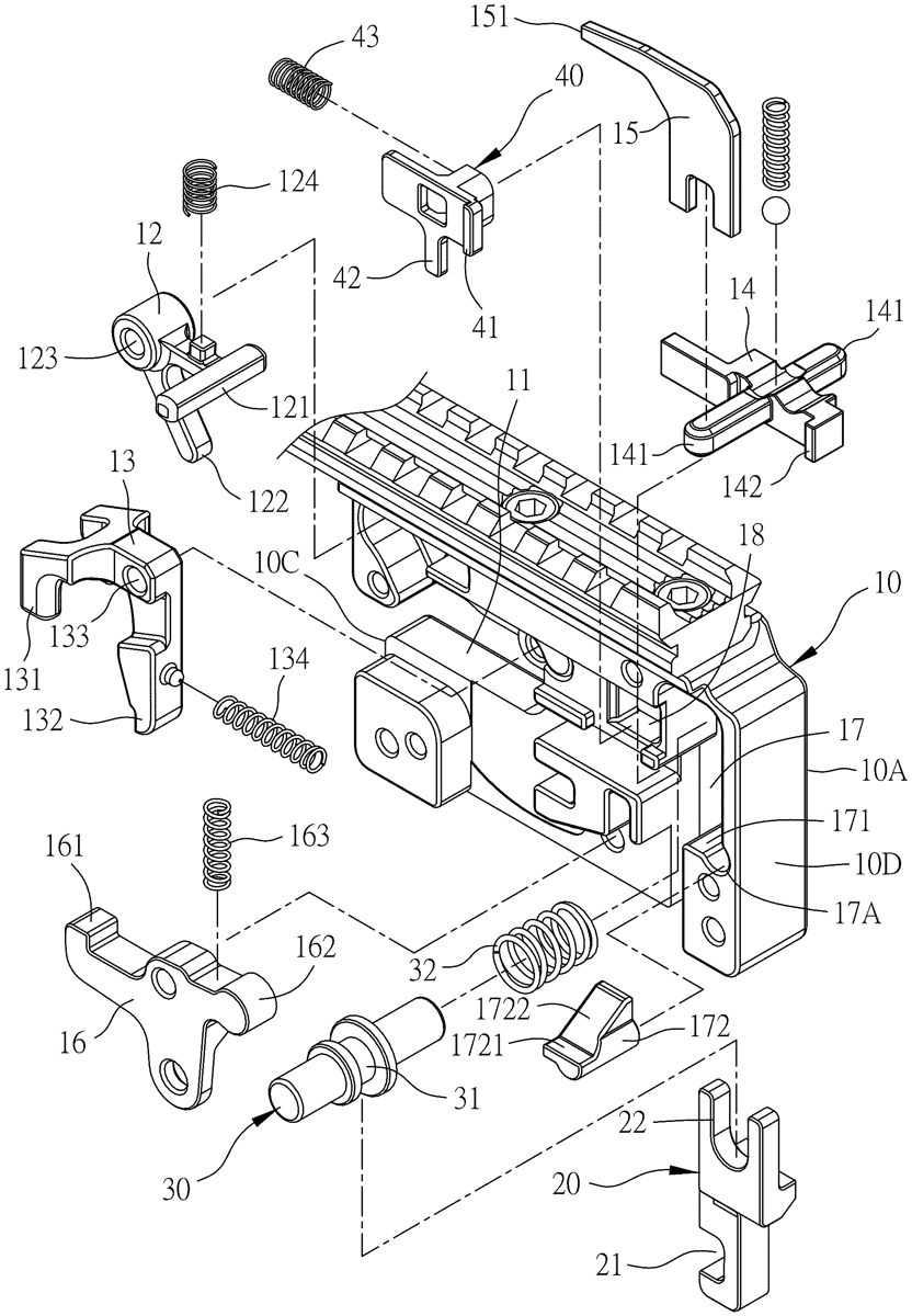
1 . A trigger reset device, comprising: a trigger block, with a front end and a rear end, and consists an arrow placement channel extending backward from a middle section of the front end, a hooker pivoted into the trigger block, a safety switch installed at a rear side of the arrow placement channel inside the trigger block, the safety switch being displaceably switchable between an open position and a closed position and having at least one slide rod extending from the safety switch, and a driving part arranged on the safety switch, the trigger block being provided with a link trigger pivoted to the inside of the trigger block and near the bottom of the trigger block, an end of the link trigger being provided with a hooking part for hooking the hooker, another end of the link trigger being provided with a link part, the trigger block comprising a linkage part receiving slot formed inside thereof and near the rear end thereof, the linkage part receiving slot comprising a displacement means, and the trigger block comprising a retractor receiving slot formed therein and configured to be corresponsive to the linkage part receiving slot; a linkage part, displaceably installed in the linkage part receiving slot of the trigger block, and having a link slot formed at the linkage part near a lower end of the linkage part, and engaged and linked with the link part of the link trigger, and a controlled part arranged at an upper end of the linkage part; a button, combined with the controlled part of the linkage part, and linked with the displacement means, and capable of driving the linkage part to move upward by pressing the button in conjunction with the displacement means, and displacing the linkage part downward to restore to its original position by releasing the button; and a retractor, installed in the retractor receiving slot of the trigger block, and comprising a positioning retainer disposed on the retractor and arranged towards an end of the linkage part, a driven part extending downward and driven by the driving part of the safety switch, and a retractor spring installed between the retractor and the trigger block, wherein the retractor is pushed by the elastic force of the retractor spring towards the linkage part to abut the linkage part; thereby, the button can be pressed to drive the linkage part to move upward, and then the linkage part drives the link trigger away from the hooker, while the linkage part and the retractor are staggered, and the retractor is moved toward the linkage part by the retractor spring, so as to block the linkage part by the positioning retainer of the retractor. a trigger block, with a front end and a rear end, and consists an arrow placement channel extending backward from a middle section of the front end, a hooker pivoted into the trigger block, a safety switch installed at a rear side of the arrow placement channel inside the trigger block, the safety switch being displaceably switchable between an open position and a closed position and having at least one slide rod extending from the safety switch, and a driving part arranged on the safety switch, the trigger block being provided with a link trigger pivoted to the inside of the trigger block and near the bottom of the trigger block, an end of the link trigger being provided with a hooking part for hooking the hooker, another end of the link trigger being provided with a link part, the trigger block comprising a linkage part receiving slot formed inside thereof and near the rear end thereof, the linkage part receiving slot comprising a displacement means, and the trigger block comprising a retractor receiving slot formed therein and configured to be corresponsive to the linkage part receiving slot; a linkage part, displaceably installed in the linkage part receiving slot of the trigger block, and having a link slot formed at the linkage part near a lower end of the linkage part, and engaged and linked with the link part of the link trigger, and a controlled part arranged at an upper end of the linkage part; a button, combined with the controlled part of the linkage part, and linked with the displacement means, and capable of driving the linkage part to move upward by pressing the button in conjunction with the displacement means, and displacing the linkage part downward to restore to its original position by releasing the button; and a retractor, installed in the retractor receiving slot of the trigger block, and comprising a positioning retainer disposed on the retractor and arranged towards an end of the linkage part, a driven part extending downward and driven by the driving part of the safety switch, and a retractor spring installed between the retractor and the trigger block, wherein the retractor is pushed by the elastic force of the retractor spring towards the linkage part to abut the linkage part; thereby, the button can be pressed to drive the linkage part to move upward, and then the linkage part drives the link trigger away from the hooker, while the linkage part and the retractor are staggered, and the retractor is moved toward the linkage part by the retractor spring, so as to block the linkage part by the positioning retainer of the retractor.
Google Patents
https://patents.google.com/patent/US12644663
USPTO PDF
https://image-ppubs.uspto.gov/dirsearch-public/print/downloadPdf/12644663