US12669695 - Adjustable-magnification viewing system
The patent describes an adjustable-magnification viewing system for scopes that integrates an afocal optical module and a display module, allowing for the observation of scenes with varying polarization states of light. This system enables the superposition of magnified and unmagnified images, enhancing the user’s visual experience while aiming.
Claim 1
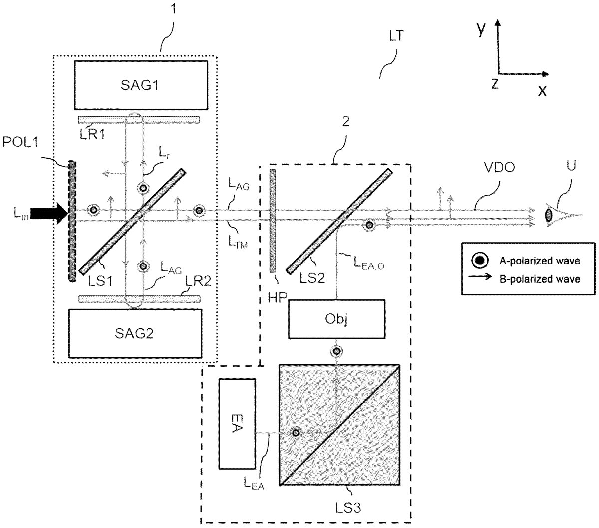
1 . A scope (LT) observing a scene, said scope comprising a first optical sub-assembly, being an afocal module, and a second optical sub-assembly, being a display module, said afocal module comprising: a removable linear polarizer (POL 1 ) that is switchable so as to transmit at least a first linear-polarization state of light (L in ) coming from said scene, called state A, or a second linear-polarization state of said light, called state B, said state B being orthogonal to said state A; a first polarization-splitting element (LS 1 ) arranged to reflect a polarization state A of light transmitted by said linear polarizer; and an afocal optical system arranged to collect light (L r ) reflected by said first polarization-splitting element, said afocal optical system comprising: a first catadioptric sub-assembly (SAG 1 ) and a second catadioptric sub-assembly (SAG 2 ), located on either side of the first polarization-splitting element, and a first retardation plate and a second retardation plate (LR 1 , LR 2 ) that are afocal, and that are arranged on the path of the reflected light (Lr), on either side of the first polarization-splitting element (LS 1 ), the first retardation plate being placed between the first polarization-splitting element (LS 1 ) and the first sub-assembly (SAG 1 ) and the second retardation plate being placed between the first polarization-splitting element (LS 1 ) and the second sub-assembly (SAG 2 ); said afocal optical system being configured to form an image of the scene with an orientation identical to an orientation of the scene observed by said scope, with a magnification greater than 1, said image being a magnified image, the first polarization-splitting element (LS 1 ) further being arranged to reflect light delivered by the second sub-assembly (SAG 2 ), being an AG light (L AG ), with a polarization state A, transporting said magnified image such that an axis of sight of the AG light is collinear with a path of light transmitted by the first polarization-splitting element, being a direct light (L TM ), with a polarization state B; said display module comprising: a half-wave plate, being a distribution plate (HP), that is arranged on the path of the AG light and direct light, after the first polarization-splitting element; a display (EA) configured to form a display image by emitting radiation, being a display light (L EA ); an optical objective (Obj) configured to collimate said display light; and a second polarization-splitting element (LS 2 ) arranged, after the distribution half-wave plate, to transmit a polarization state B, of the direct light or of the AG light, while spatially combining it with the collimated display light (L EA,O ), so that said scope superposes said unmagnified image or said direct light with said display image. said afocal module comprising: a removable linear polarizer (POL 1 ) that is switchable so as to transmit at least a first linear-polarization state of light (L in ) coming from said scene, called state A, or a second linear-polarization state of said light, called state B, said state B being orthogonal to said state A; a first polarization-splitting element (LS 1 ) arranged to reflect a polarization state A of light transmitted by said linear polarizer; and an afocal optical system arranged to collect light (L r ) reflected by said first polarization-splitting element, said afocal optical system comprising: a first catadioptric sub-assembly (SAG 1 ) and a second catadioptric sub-assembly (SAG 2 ), located on either side of the first polarization-splitting element, and a first retardation plate and a second retardation plate (LR 1 , LR 2 ) that are afocal, and that are arranged on the path of the reflected light (Lr), on either side of the first polarization-splitting element (LS 1 ), the first retardation plate being placed between the first polarization-splitting element (LS 1 ) and the first sub-assembly (SAG 1 ) and the second retardation plate being placed between the first polarization-splitting element (LS 1 ) and the second sub-assembly (SAG 2 ); a removable linear polarizer (POL 1 ) that is switchable so as to transmit at least a first linear-polarization state of light (L in ) coming from said scene, called state A, or a second linear-polarization state of said light, called state B, said state B being orthogonal to said state A; a first polarization-splitting element (LS 1 ) arranged to reflect a polarization state A of light transmitted by said linear polarizer; and an afocal optical system arranged to collect light (L r ) reflected by said first polarization-splitting element, said afocal optical system comprising: a first catadioptric sub-assembly (SAG 1 ) and a second catadioptric sub-assembly (SAG 2 ), located on either side of the first polarization-splitting element, and a first retardation plate and a second retardation plate (LR 1 , LR 2 ) that are afocal, and that are arranged on the path of the reflected light (Lr), on either side of the first polarization-splitting element (LS 1 ), the first retardation plate being placed between the first polarization-splitting element (LS 1 ) and the first sub-assembly (SAG 1 ) and the second retardation plate being placed between the first polarization-splitting element (LS 1 ) and the second sub-assembly (SAG 2 ); a first catadioptric sub-assembly (SAG 1 ) and a second catadioptric sub-assembly (SAG 2 ), located on either side of the first polarization-splitting element, and a first retardation plate and a second retardation plate (LR 1 , LR 2 ) that are afocal, and that are arranged on the path of the reflected light (Lr), on either side of the first polarization-splitting element (LS 1 ), the first retardation plate being placed between the first polarization-splitting element (LS 1 ) and the first sub-assembly (SAG 1 ) and the second retardation plate being placed between the first polarization-splitting element (LS 1 ) and the second sub-assembly (SAG 2 ); said afocal optical system being configured to form an image of the scene with an orientation identical to an orientation of the scene observed by said scope, with a magnification greater than 1, said image being a magnified image, the first polarization-splitting element (LS 1 ) further being arranged to reflect light delivered by the second sub-assembly (SAG 2 ), being an AG light (L AG ), with a polarization state A, transporting said magnified image such that an axis of sight of the AG light is collinear with a path of light transmitted by the first polarization-splitting element, being a direct light (L TM ), with a polarization state B; said display module comprising: a half-wave plate, being a distribution plate (HP), that is arranged on the path of the AG light and direct light, after the first polarization-splitting element; a display (EA) configured to form a display image by emitting radiation, being a display light (L EA ); an optical objective (Obj) configured to collimate said display light; and a second polarization-splitting element (LS 2 ) arranged, after the distribution half-wave plate, to transmit a polarization state B, of the direct light or of the AG light, while spatially combining it with the collimated display light (L EA,O ), so that said scope superposes said unmagnified image or said direct light with said display image. a half-wave plate, being a distribution plate (HP), that is arranged on the path of the AG light and direct light, after the first polarization-splitting element; a display (EA) configured to form a display image by emitting radiation, being a display light (L EA ); an optical objective (Obj) configured to collimate said display light; and a second polarization-splitting element (LS 2 ) arranged, after the distribution half-wave plate, to transmit a polarization state B, of the direct light or of the AG light, while spatially combining it with the collimated display light (L EA,O ), so that said scope superposes said unmagnified image or said direct light with said display image.
Google Patents
https://patents.google.com/patent/US12669695
USPTO PDF
https://image-ppubs.uspto.gov/dirsearch-public/print/downloadPdf/12669695