US12650279 - Grenade launcher
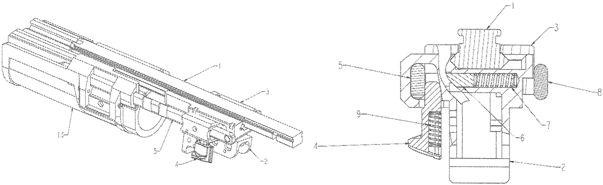
The patent describes a grenade launcher featuring a barrel, trigger mechanism base, and breech designed for mounting on a host rail interface, with guide rails facilitating the sliding attachment of the barrel. The breech includes a cavity that secures one of the guide rails using a detent and a pin, which is spring-loaded to ensure stability during operation.
Claim 1
1 . A grenade launcher, comprising a barrel, a trigger mechanism base and a breech wherein the trigger mechanism base is adapted to be mounted on a host rail interface, and on the opposed sides of the trigger mechanism base, guide rails are arranged for sliding mounting of the barrel, the breech and the trigger mechanism base are configured to clamp the host rail interface, and the breech is fitted with a cavity that surrounds one of the guide rails and an inner wall of the cavity is pressed to the guide rail by a detent that is insertable between the guide rail and an opposed inner wall of the cavity, the opposed inner wall of the cavity is inclined in a wedge-like way and a pin bears on the guide rail from the inner side, the pin being mounted in a sliding way in a recess transversally in the breech, and the pin fitted with a compression spring.
Google Patents
https://patents.google.com/patent/US12650279
USPTO PDF
https://image-ppubs.uspto.gov/dirsearch-public/print/downloadPdf/12650279