US12663238 - Adjustment turret for a riflescope
The patent describes an adjustment turret for riflescopes that features a rotatable adjusting ring and an actuation element, which allows for two-way adjustment and establishes end stops for each direction of rotation. This design enhances user control over the scope’s settings by providing distinct positions for the actuation element based on the direction of rotation.
Claim 1
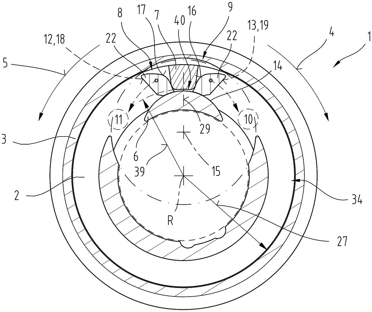
1 . An adjustment turret ( 1 ) for a riflescope, comprising; a base socket ( 2 ) for mounting on the riflescope; an adjusting ring ( 3 ), wherein the adjusting ring ( 3 ) is rotatable about an axis of rotation (R) relative to the base socket ( 2 ) in a first direction of rotation ( 4 ), as well as in an opposite second direction of rotation ( 5 ), wherein an actuator element can be actuated by means of the rotation of the adjusting ring ( 3 ); wherein an actuation element ( 8 ) is arranged between the adjusting ring ( 3 ) and the base socket ( 2 ), wherein the actuation element ( 8 ) is adjustable from a first position ( 10 ) to a second position ( 11 ) by means of the rotation of the adjusting ring ( 3 ) in the first direction of rotation ( 4 ), and is adjustable from the second position ( 11 ) to the first position ( 10 ) during the rotation of the adjusting ring ( 3 ) in the second direction of rotation ( 5 ), and wherein, by means of the actuation element ( 8 ), in its first position ( 10 ), a first end stop ( 12 ) for the rotation of the adjusting ring ( 3 ) by a predetermined amount in the second direction of rotation ( 5 ) is formed, and, in its second position ( 11 ), a second end stop ( 13 ) for the rotation of the adjusting ring ( 3 ) by a predetermined amount in the first direction of rotation ( 4 ) is formed. a base socket ( 2 ) for mounting on the riflescope; an adjusting ring ( 3 ), wherein the adjusting ring ( 3 ) is rotatable about an axis of rotation (R) relative to the base socket ( 2 ) in a first direction of rotation ( 4 ), as well as in an opposite second direction of rotation ( 5 ), wherein an actuator element can be actuated by means of the rotation of the adjusting ring ( 3 ); wherein an actuation element ( 8 ) is arranged between the adjusting ring ( 3 ) and the base socket ( 2 ), wherein the actuation element ( 8 ) is adjustable from a first position ( 10 ) to a second position ( 11 ) by means of the rotation of the adjusting ring ( 3 ) in the first direction of rotation ( 4 ), and is adjustable from the second position ( 11 ) to the first position ( 10 ) during the rotation of the adjusting ring ( 3 ) in the second direction of rotation ( 5 ), and wherein, by means of the actuation element ( 8 ), in its first position ( 10 ), a first end stop ( 12 ) for the rotation of the adjusting ring ( 3 ) by a predetermined amount in the second direction of rotation ( 5 ) is formed, and, in its second position ( 11 ), a second end stop ( 13 ) for the rotation of the adjusting ring ( 3 ) by a predetermined amount in the first direction of rotation ( 4 ) is formed.
Google Patents
https://patents.google.com/patent/US12663238
USPTO PDF
https://image-ppubs.uspto.gov/dirsearch-public/print/downloadPdf/12663238