US12643731 - Dispensers for spraying chemical irritants and methods of using
The patent describes a dispenser designed for spraying chemical irritants, featuring a casing with an interior cavity that holds a canister and an actuator for releasing the irritant. The actuator is retained by a mechanism that allows for its removal when a specific wall is deflected, enabling the foot of a resilient leg to bypass a radial shoulder within the casing.
Claim 1
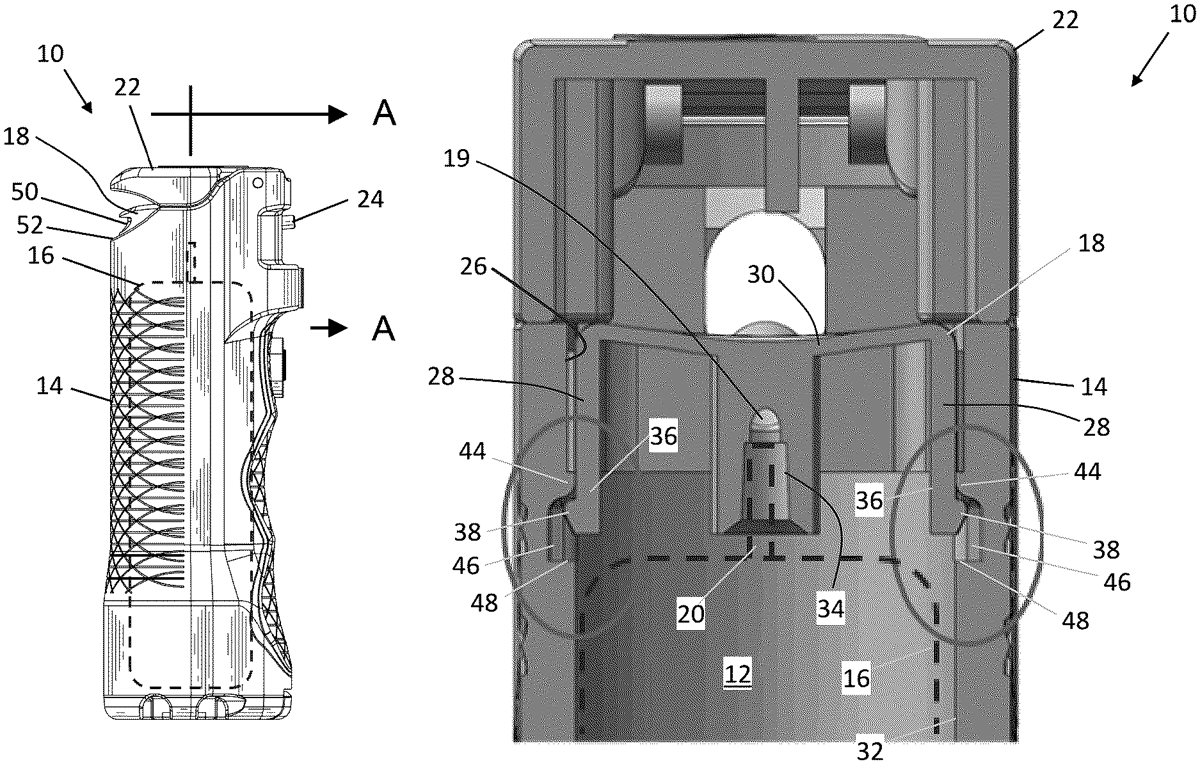
1 . A dispenser for spraying a chemical irritant, the dispenser comprising: a casing having an upper end and a lower end disposed on a longitudinal axis of the casing, the casing having an interior cavity between the upper and lower ends and an access opening to the interior cavity disposed at the upper end of the casing, the interior cavity being configured to receive a cannister with a product release valve oriented toward the access opening in an operative configuration; an actuator slidingly disposed in the access opening for actuating the product release valve; and a retention mechanism for releasably retaining the actuator in the access opening, the retention mechanism comprising: a top wall and a sidewall of the actuator; a resilient leg axially extending from the sidewall, the resilient leg having a foot extending radially outward from the resilient leg; and a radial shoulder extending radially inward from an interior wall of the interior cavity, the radial shoulder capturing the foot of the resilient leg so as to inhibit removal of the actuator from the access opening of the casing; wherein the top wall of the actuator is operable to be deflected so as to cause the resilient leg to sufficiently deflect radially inward to enable the foot to travel over and past the radial shoulder and thereby allow the actuator to slide out through the access opening. a casing having an upper end and a lower end disposed on a longitudinal axis of the casing, the casing having an interior cavity between the upper and lower ends and an access opening to the interior cavity disposed at the upper end of the casing, the interior cavity being configured to receive a cannister with a product release valve oriented toward the access opening in an operative configuration; an actuator slidingly disposed in the access opening for actuating the product release valve; and a retention mechanism for releasably retaining the actuator in the access opening, the retention mechanism comprising: a top wall and a sidewall of the actuator; a resilient leg axially extending from the sidewall, the resilient leg having a foot extending radially outward from the resilient leg; and a radial shoulder extending radially inward from an interior wall of the interior cavity, the radial shoulder capturing the foot of the resilient leg so as to inhibit removal of the actuator from the access opening of the casing; wherein the top wall of the actuator is operable to be deflected so as to cause the resilient leg to sufficiently deflect radially inward to enable the foot to travel over and past the radial shoulder and thereby allow the actuator to slide out through the access opening. a top wall and a sidewall of the actuator; a resilient leg axially extending from the sidewall, the resilient leg having a foot extending radially outward from the resilient leg; and a radial shoulder extending radially inward from an interior wall of the interior cavity, the radial shoulder capturing the foot of the resilient leg so as to inhibit removal of the actuator from the access opening of the casing; wherein the top wall of the actuator is operable to be deflected so as to cause the resilient leg to sufficiently deflect radially inward to enable the foot to travel over and past the radial shoulder and thereby allow the actuator to slide out through the access opening.
Google Patents
https://patents.google.com/patent/US12643731
USPTO PDF
https://image-ppubs.uspto.gov/dirsearch-public/print/downloadPdf/12643731