Oct 20, 2026
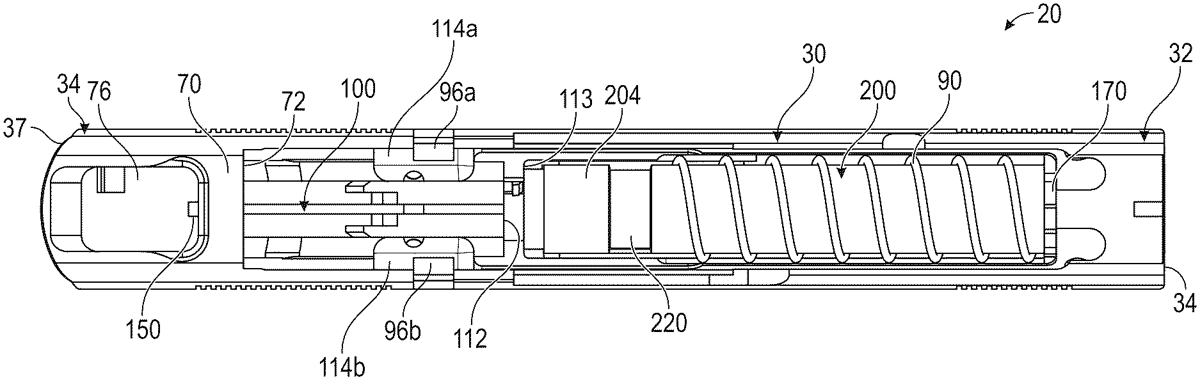
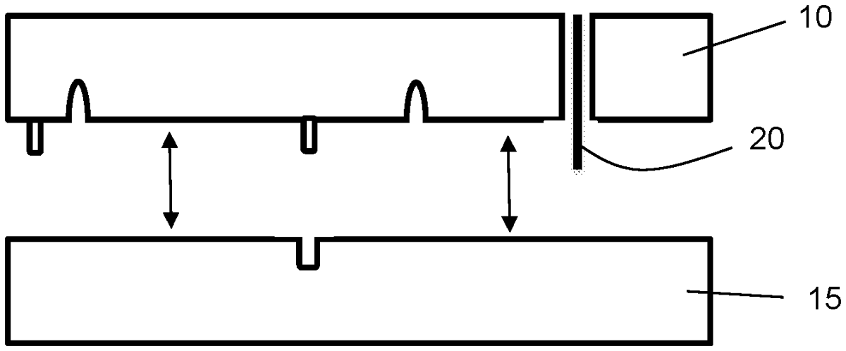
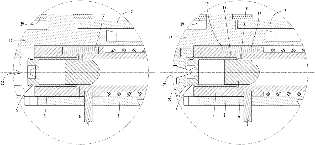
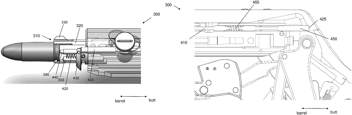
A firearm comprising of a chassis, a barrel, a slide, and a reciprocating block connected to the chassis. The reciprocating block is operable to reciprocate with respect to the barrel between a chamber open position in which a face portion of the block is spaced apart from the breech end of the barrel and a chamber closed position in which the face portion of the block is proximate the breech end of the barre. A locking element selectively engages the slide and the block and operable to prevent rearward movement of the block when the slide is in the battery position, and to enable rearward movement of the block when the slide has moved rearward with respect to the block by a limited distance to an intermediate position forward of the recoil position.
Oct 20, 2026
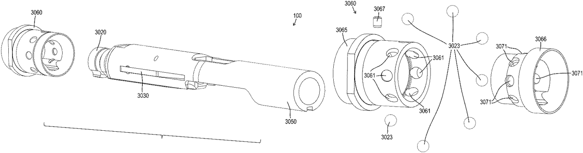
Improvements in a ballistic with a multi-part chamber locking assembly is disclosed to allow the casing ejection and reloading sequence to be temporarily slowed down to capture the optimum amount of ignited gun powders expanding gas, prior to the round exiting the barrel. Large slide component(s) of a firearm are replaced with a multi-part chamber locking assembly. This negates the requirement for a round to move laterally after moving vertically. The round only moves vertically thus mitigating the requirement for any forward motion. The multi-part chamber reduces the weight and materials needed to actuate all components of the ejecting and reloading process, so more energy is available to transfer movement of casing ejecting. The round is fired with a hammer or striker through impingement or a firing pin actuated action on a primer to ignite the propellant.
Oct 13, 2026
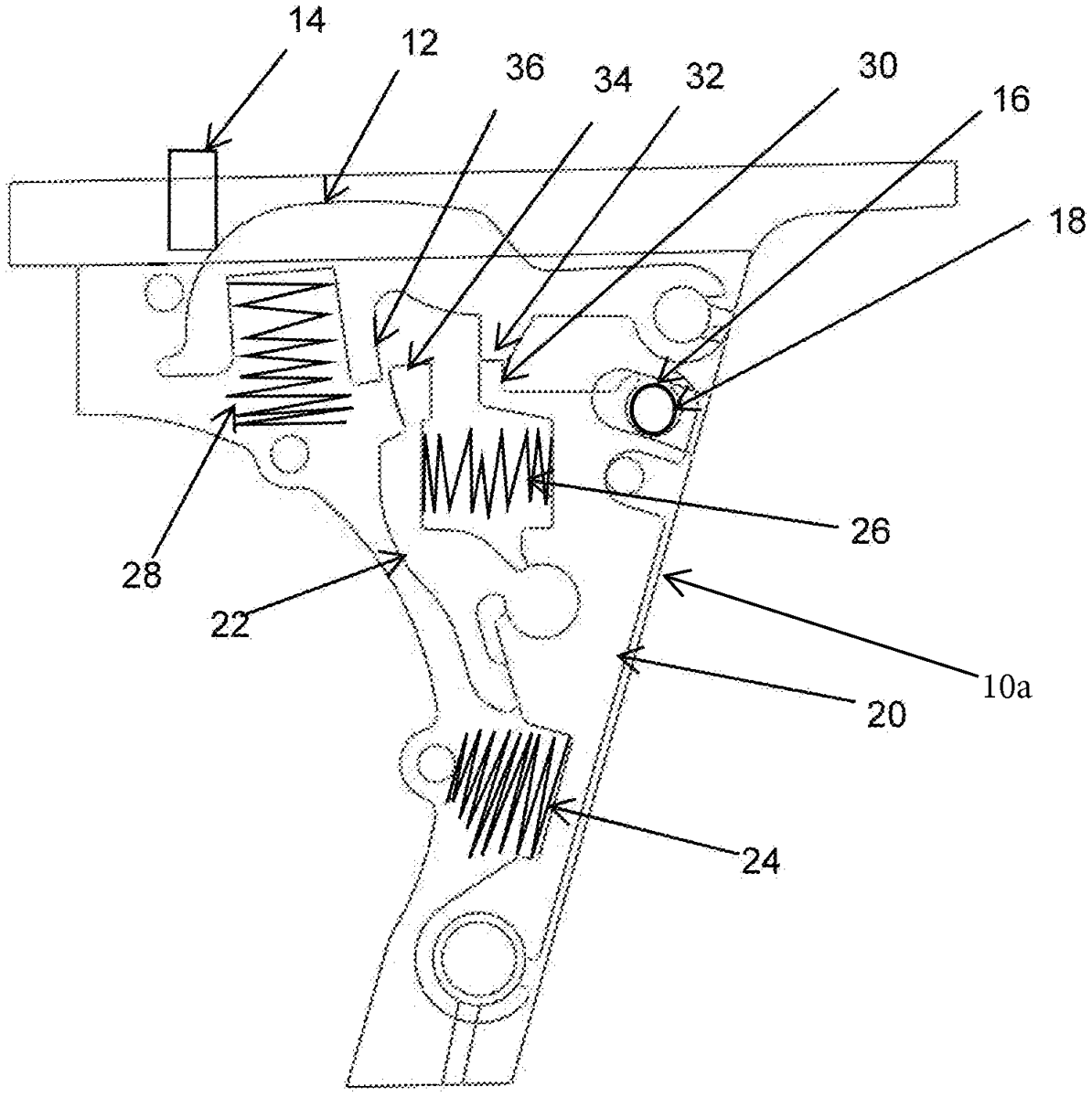
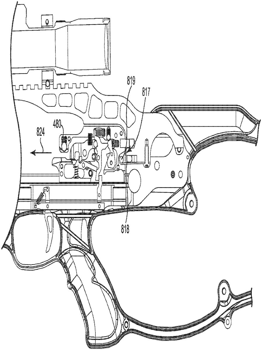
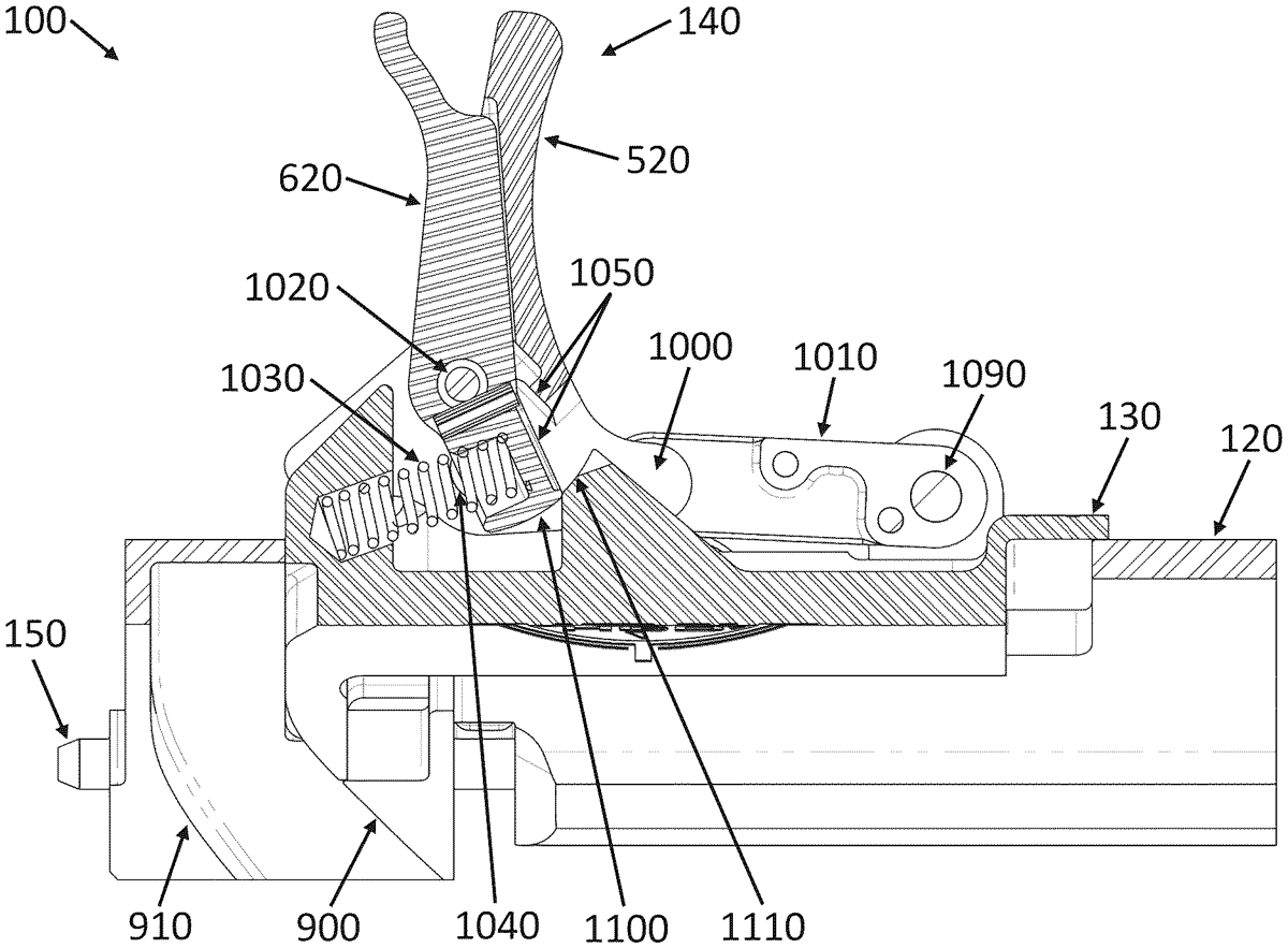
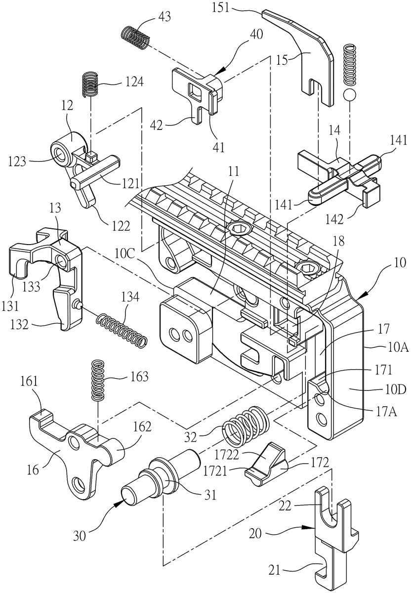
A non-skip trigger for a sliding weapon including a spring-loaded pivot arm, spring loaded disconnector, and spring-loaded firing pin release that fit together to prevent automatic firing of the weapon.
Oct 13, 2026
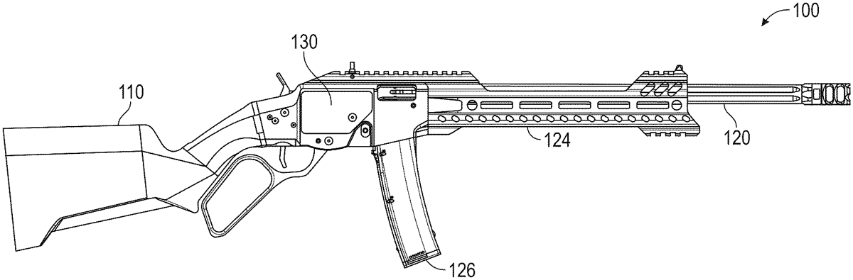
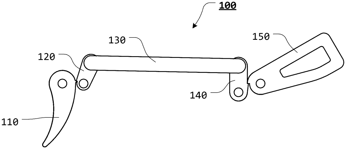
Rifles of the present disclosure may comprise a stock a, a receiver assembly, and a barrel. The receiver assembly may comprise a bolt, a trigger system, a lever, and a linkage. The receiver assembly installed in the stock. The linkage may comprise a first link having a first end and a second end, the first end rotatably coupled to the bolt. The linkage may further comprise a second link have a third end and a fourth end, the third end being rotatably coupled to the second end. The linkage may also comprise a third link having a fifth end and two arms coupled to the fifth end defining a channel, the fifth end rotatably coupled to the fourth end. The lever being slidably installed in the channel and configured to move the bolt between an in-battery and an out-of-battery position.
Oct 13, 2026
A system and method for adding and removing a roll pin from a firearm. The system comprises an upper plate defined by a top surface and an opposed bottom surface. The bottom surface comprises at least one punch insert sized and shaped to remove a roll pin from a corresponding bore hole in a firearm. The bottom surface also includes at least one punch pin configured to releasably hold a first end of a roll pin. The system also includes a lower plate defined by a top surface and a bottom surface, wherein the top surface includes a channel that passes through the lower plate.
Oct 6, 2026
A crossbow including a riser, a limb coupled to the riser, and a cam assembly rotatably coupled to the limb about an axis of rotation. The cam assembly including a string guide defining a plane of rotation of the cam assembly about the axis of rotation and structured to support a drawstring, a drawstring attachment point structured to engage the drawstring, a power cable journal extending away from the plane of rotation along the axis of rotation and structured to support a power cable, and a power cable attachment point structured to engage the power cable. The power cable journal is shaped to displace the power cable away from the plane of rotation as the crossbow is drawn from a released configuration to a drawn configuration to provide a gap sized to permit the drawstring attachment point and the power cable attachment point to pass between the power cable and the plane of rotation.
Oct 6, 2026
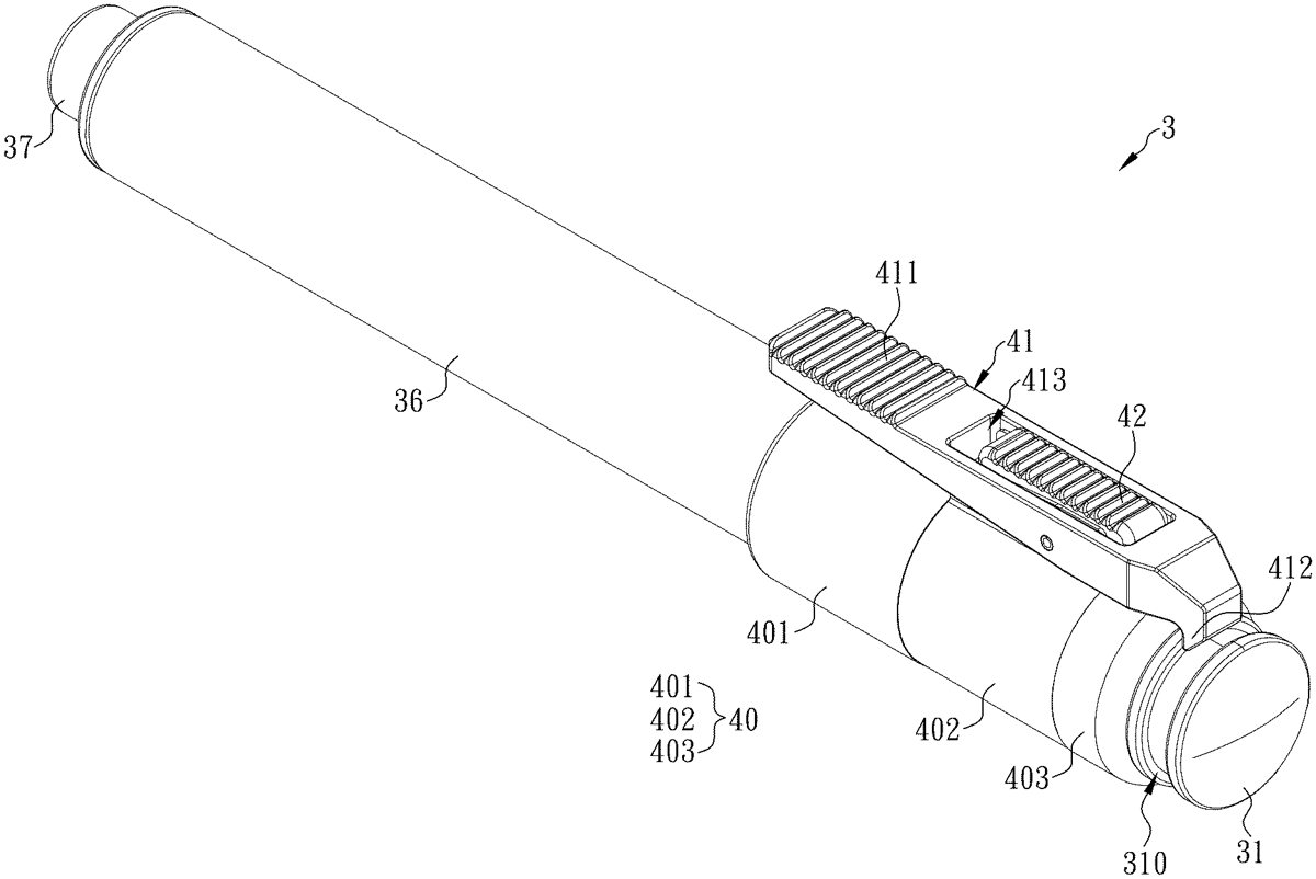
A safety locking mechanism is applicable to an elastically expandable baton including a plurality of hollow tubes that can be collapsed into a short baton or expanded into a long baton. The safety locking mechanism includes a positioning portion that can be fixed to one of the hollow tubes, a locking-releasing button pivotally connectable to the positioning portion, and a safety locking key arranged to the locking-releasing button. A user only needs to push the safety locking key with a finger and makes the safety locking key to be in a locking position, the locking-releasing button will not be able to move as a lever, thereby keeping the elastically expandable baton in the short-baton state.
Oct 6, 2026
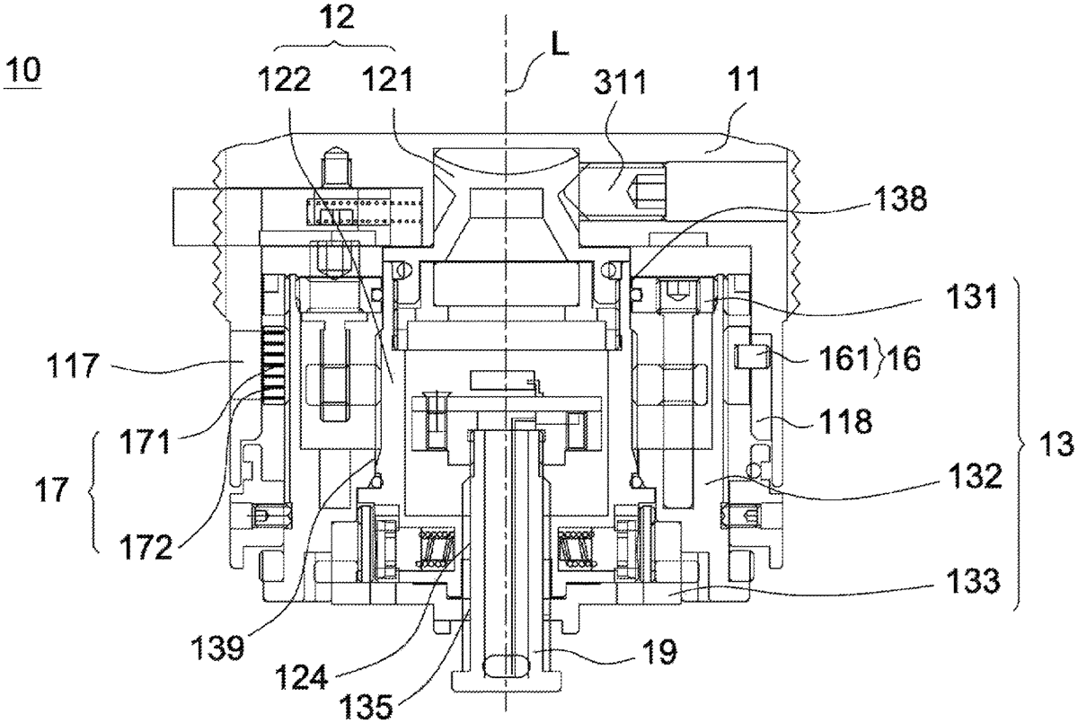
A sight includes a compensating mechanism. The compensating mechanism includes a base unit, a displaying unit, an adjusting cap and a first transmission unit. The displaying unit is disposed on the base unit and includes a mark. The adjusting cap is disposed outside the displaying unit and includes an information displaying portion for showing the mark. The first transmission unit is connected to the adjusting cap and the displaying unit. The adjusting cap is connected to the transmission unit and includes a groove. When the adjusting cap is rotated with respect to the base unit about an axis, the information displaying portion is synchronously rotated with the adjusting cap and the first transmission unit drives the displaying unit to move along the axis so as to change the mark shown by the information displaying portion.
Sep 29, 2026
A firearm operating system includes a bolt with at least one bearing cavity, a carrier disposed on a rear side of the bolt, a plurality of bearings, and a barrel extension. The carrier includes a cavity. The plurality of bearings are retained in the barrel extension. The plurality of bearings are movable relative to the barrel extension.
Sep 15, 2026
The present disclosure relates to a torso of a support device. The torso may include an axle assembly including an axle block and an axle passing through the axle block. The torso may also include a pelvic block assembly that includes a first pelvic block and a second pelvic block overlapping with the first pelvic block, the axle passing through the first pelvic block and the second pelvic block. The torso also includes a spreader pin passing through a spreader pin hole of the pelvic block assembly, the spreader pin and spreader pin hole being configured to adjust an angle between the first pelvic block and the second pelvic block.
Sep 15, 2026
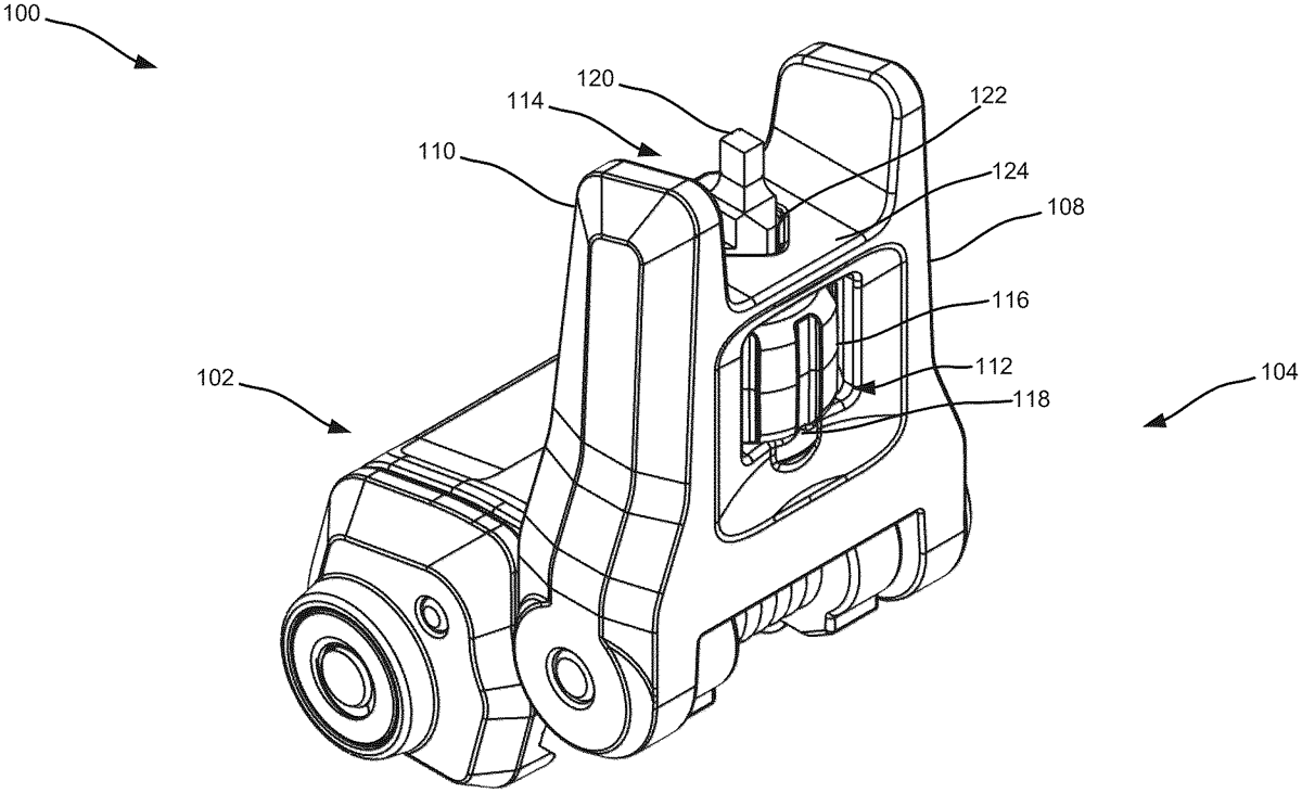
A sighting system for a firearm and related methods are disclosed. The sighting system has front and rear flip-up sights, wherein the front sight comprises a flip-up portion having an aperture through which a sight post can partially extend; a knob comprising one or more notches on a first side and the sight post extending from a second side; at least one detent arranged to face and interact with the one or more notches. The knob is configured to rotate about a first axis, where the rotation causes the sight post to move in a first direction along the first axis; tilting of the knob in a second direction based on the detent interfacing with the notches; and tilting of the sight post in the second direction, thereby forcing at least a portion of the sight post to press against the aperture, or a combination thereof.
Sep 1, 2026
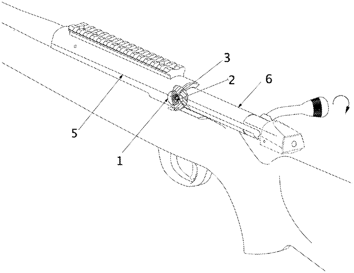
Disclosed is a mechanism disassembly device for weapons with a bolt mechanism, which allows the mechanisms to be removed and installed from the body with one hand, without a button.
Sep 1, 2026
A trigger mechanism, including a trigger having a trigger shoulder; a trigger sear having a trigger sear shoulder, and wherein the trigger and the trigger sear are positioned such that at least a portion of the trigger shoulder is able to at least partially contact at least a portion of the trigger sear shoulder; a hammer sear having a hammer sear shoulder; a hammer having a hammer shoulder, and wherein the hammer and the hammer sear are positioned such that at least a portion of the hammer shoulder is able to at least partially contact at least a portion of the hammer sear shoulder; and a trigger bar, wherein if the trigger is rotated, the trigger releases the trigger sear, which, urges the trigger bar, which, rotates the hammer sear, which, releases the hammer.
Sep 1, 2026
The present invention relates to a training firearm and more specifically, to a training firearm that mimics the trigger mechanism of real firearms. The training firearm comprises a frame, a break arm, a movable magnate, a frame magnet, a trigger, a reed switch and a shot indicator. On application of force, the trigger pushes the break arm to move the movable magnate closer to the reed switch. Once the magnetic field of moveable magnate is detected by the reed switch it turn on the shot indicator to shoot a laser.
Sep 1, 2026
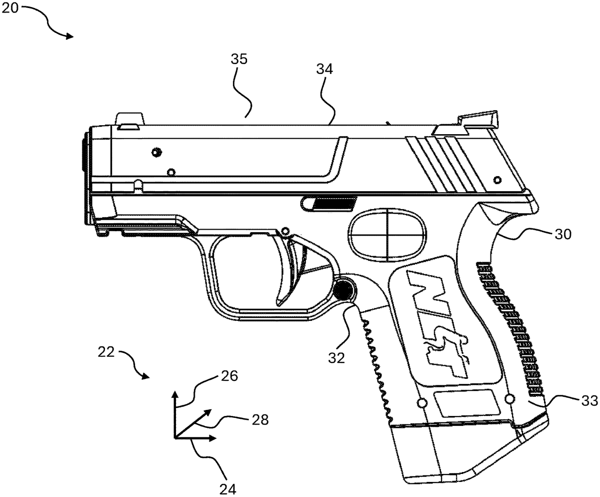
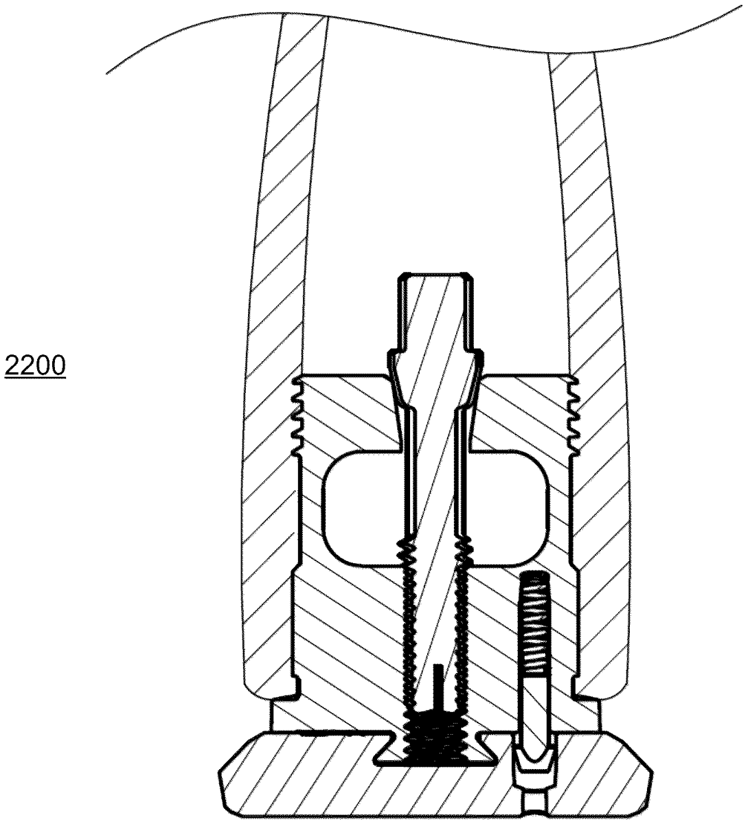
In various embodiments, an apparatus to operate with a firearm grip is provided, in which the firearm grip includes two openings, including a magazine receptacle and an aftly-positioned additional opening, the openings partitioned by a wall, the apparatus comprising: a retention system insertable into the aftly-positioned additional opening, the retention system including: a drive section; and an expansion section, driven by the drive section, and configured to restrict expansion to direction(s) that are not toward the wall. Other embodiments are disclosed and/or claimed.
Sep 1, 2026
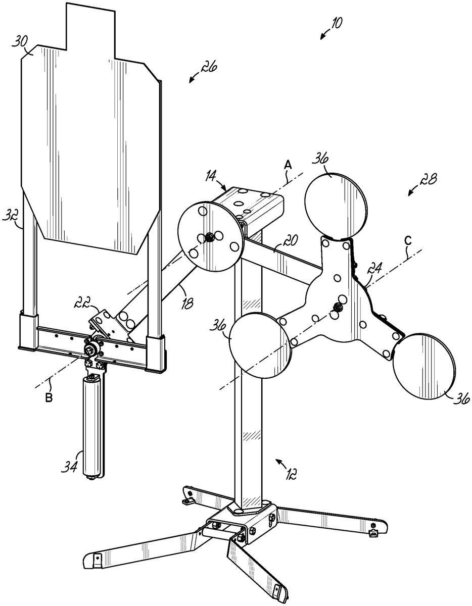
A swinging target device has a stand, an arm having a first end and a second end and pivoted to the stand between the first and second ends for pivoting movement about a primary pivot axis. A first target assembly is pivoted to the first end of the arm for pivoting movement about a first secondary pivot axis, and a second target assembly is pivoted to the second end of the arm for pivoting movement about a second secondary pivot axis.
Aug 25, 2026
The present invention relates to a firearm, which includes a receiver and a barrel mountable to the receiver. A slide is mountable to the receiver so as to be movable between an open position and a closed position. A locking element is operatively associated with the barrel. The locking element is displaceable between an inactive position and an active position whereby, when the locking element is in the active position, the locking element engages the slide such that movement of the slide towards the open position is inhibited.
Aug 25, 2026
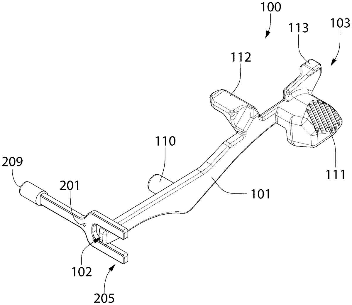
A firearm with ambidextrous bolt release mechanism includes a barrel and a bolt slideably mounted in the receiver for axial movement between forward closed breech position in battery with the barrel and a rearward open breech position. A recoil spring biases the bolt forward. A side-mounted bolt catch lever is configured and operable to selectively hold the bolt in the open breech position, and disengage the bolt to reclose the breech when manually actuated. A transversely movable actuator plunger allows a user to release the bolt from the side of the firearm opposite the bolt catch lever side. The plunger comprises an inclined camming surface which slideably engages a mating inclined camming ramp on the lever. Wedging action applied to the bolt catch lever by the plunger rotates the lever about its pivot axis to disengage and release the bolt.
Aug 25, 2026
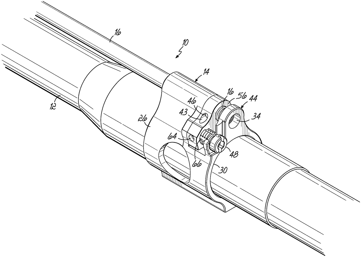
Disclosed is a firearm gas system including a gas block having a body with gas passageway for alignment with a barrel gas port. A gas tube has a gas inlet in a forward portion thereof and is axially variably positionable in at least partial alignment and disalignment relative to the gas passageway to thereby adjust gas flow.
Aug 25, 2026
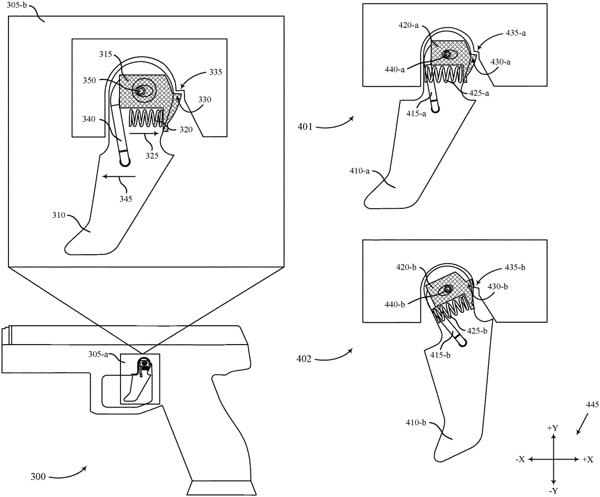
The present disclosure provides systems and techniques for a trigger system that can be implemented in a gun. The trigger system may include a trigger body affixed to a pivot, a trigger detent affixed to the pivot, and a detent biasing device configured to bias the trigger detent away from the trigger body such that a detent surface protrudes from the trigger body. The trigger detent may be moveable along a displacement path, and an obstructing surface that is configured to remain substantially stationary relative to the trigger detent may be located in the displacement path of the trigger detent. The trigger detent may be configured to contact the obstructing surface while moving along the displacement path, move linearly away from the obstructing surface by compressing the detent biasing device, and move past the obstructing surface based on a threshold amount of force being applied to the trigger body.
Aug 25, 2026
A device may include a proximal end and a distal end, an internal cavity of the device is defined between the proximal end and the distal end. The device may include a slider panel defining a channel and a biasing mechanism disposed in the internal cavity, the biasing mechanism configured to bias the slider panel. The device may include a lock pin disposed in the internal cavity and configured to contact the biasing mechanism. The device may include a release pin extending through the lock pin, wherein: an end portion of the release pin extends into the channel, the release pin is configured to travel along a path defined by the channel in response to a movement of the slider panel; and the release pin is configured to cause the lock pin to transition from a first position to a second position in response to the movement.
Aug 18, 2026
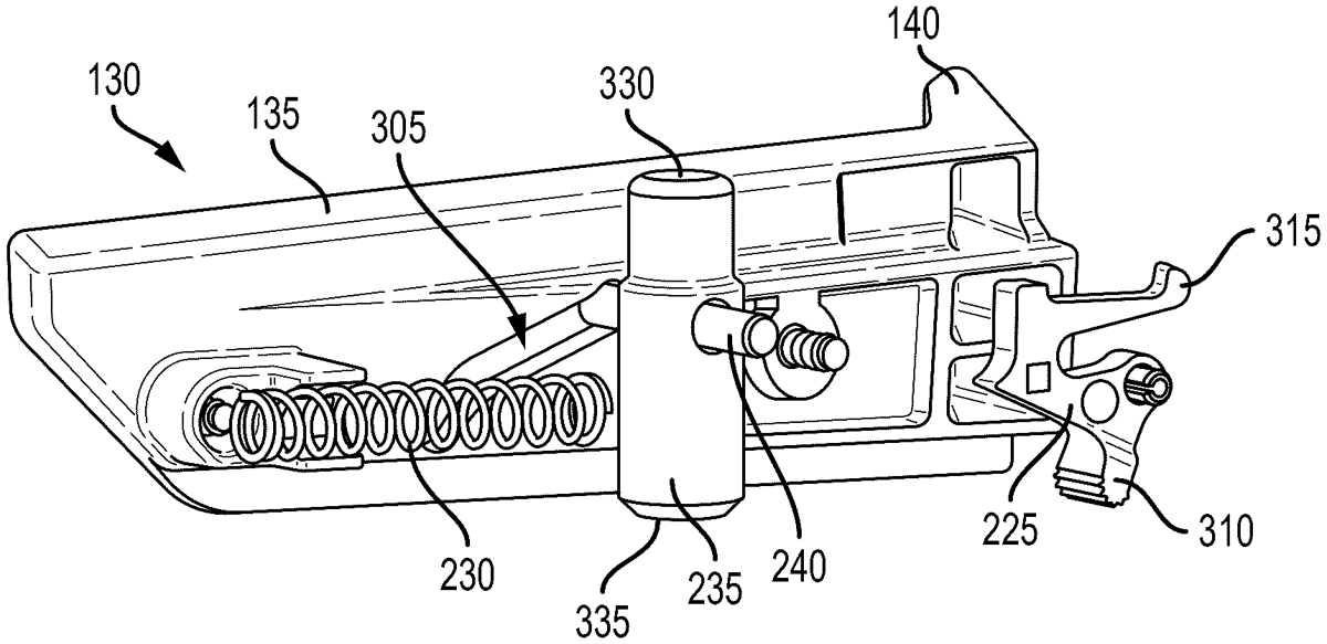
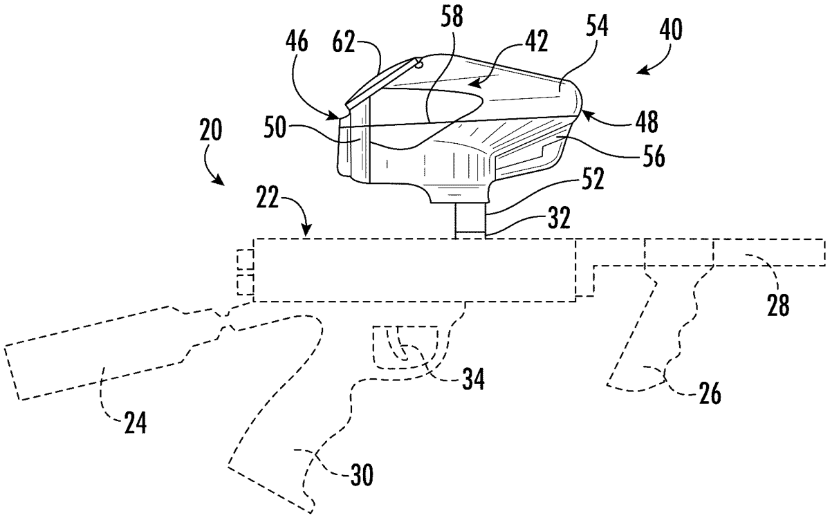
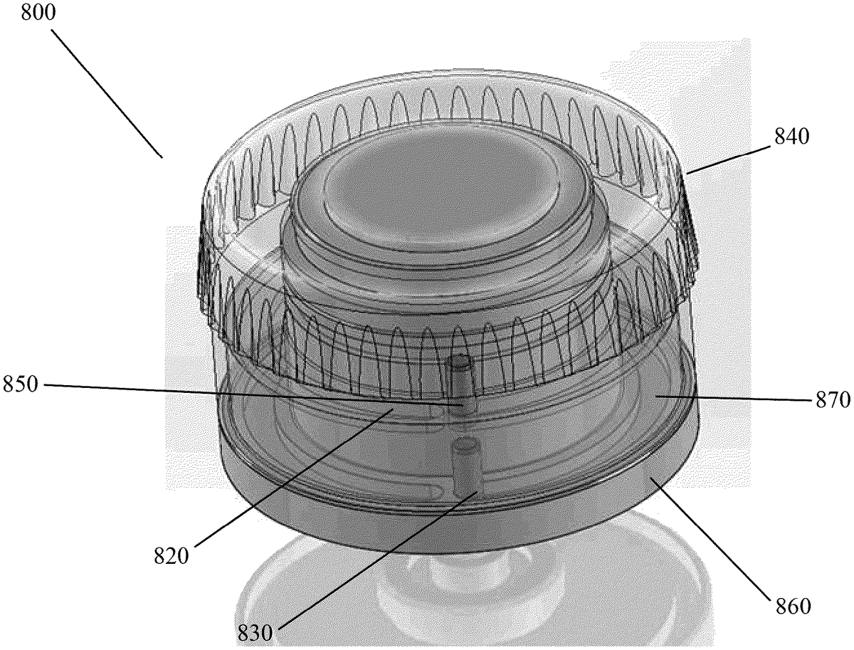
A projectile loader is provided having a body split into two portions, a locking mechanism, a quick release carrier, and a retaining system. The locking mechanism is provided within the projectile loader for locking the two portions of the projectile loader body. The quick release carrier of a feed system is provided within the projectile loader for preventing jams, among other issues, within the projectile loader. The retaining system is provided within the projectile loader for ensuring the feed system remains secured within the body during use of the projectile loader.
Aug 18, 2026
In one embodiment, the disclosure relates to a turret for a firearm. In another embodiment, the disclosure relates to a turret zero stop.
Aug 18, 2026
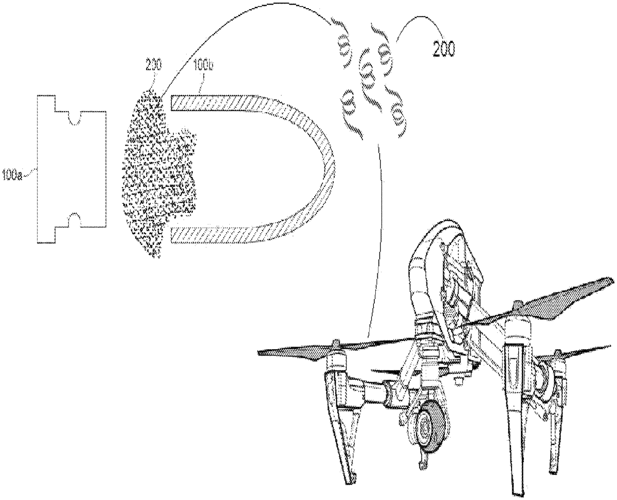
A device may include a set of payloads and a mechanism. The set of payloads may be configured to interact with at least one of an airborne device or a component of the airborne device via at least one of physical entanglement, sensor obscuration, or surface adhesion. The mechanism may be operable between an inactive state and an active state. The mechanism may be configured to transition to the active state in response to inductive energy generated by relative motion through a magnetic field during launch, and deploy the set of payloads based on at least one of one or more elapsed times during travel of the device along the trajectory, one or more positions of the device along the trajectory, or one or more distances traveled by the device along the trajectory.
Aug 11, 2026
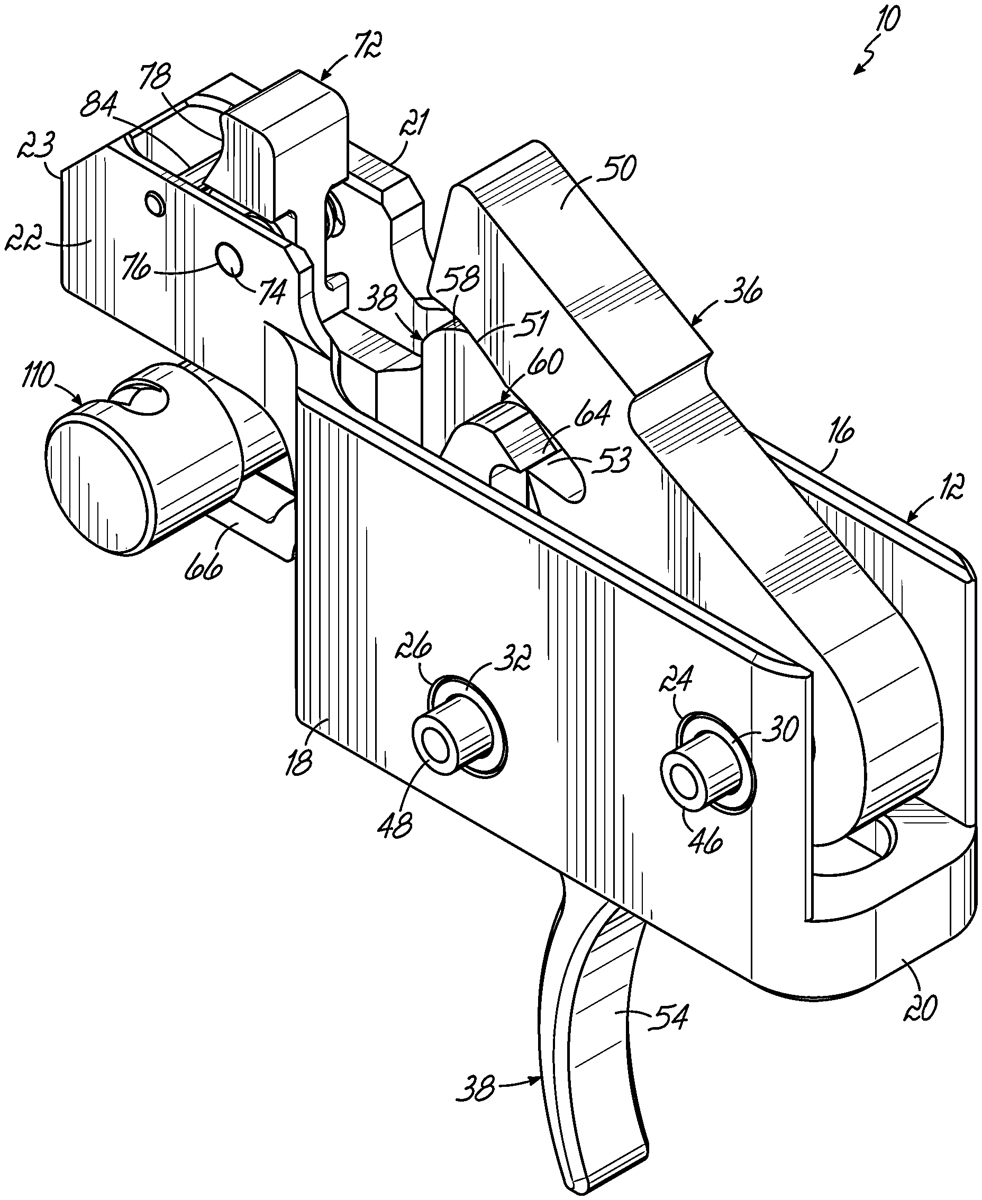
A trigger device for activating a firing mechanism is described. The trigger device comprises a housing, a sear, and a trigger. The sear is pivotally mounted on the housing via a sear pivot pin. The trigger is pivotally mounted on the housing via a trigger pivot pin. The trigger comprises a trigger extender. The trigger extender inhibits unloading the sear until the trigger is rotated from a ready position.
Aug 11, 2026
A sear assembly for a weapon, the weapon comprising a hammer adapted to contact with the sear assembly and a trigger disconnected from the sear assembly, the sear assembly comprises a sear for mechanically engaging a sear surface on the hammer, a lever mechanically coupled by one end to the sear, the lever comprising a contact surface that causes the rotation of the sear, an actuator that actuates the lever by means of a cam, and a trigger sensor that is configured to determine if the trigger is pulled. In this regard, the trigger sensor is a coil. The sear assembly comprises a firing state and a safe state.
Aug 4, 2026
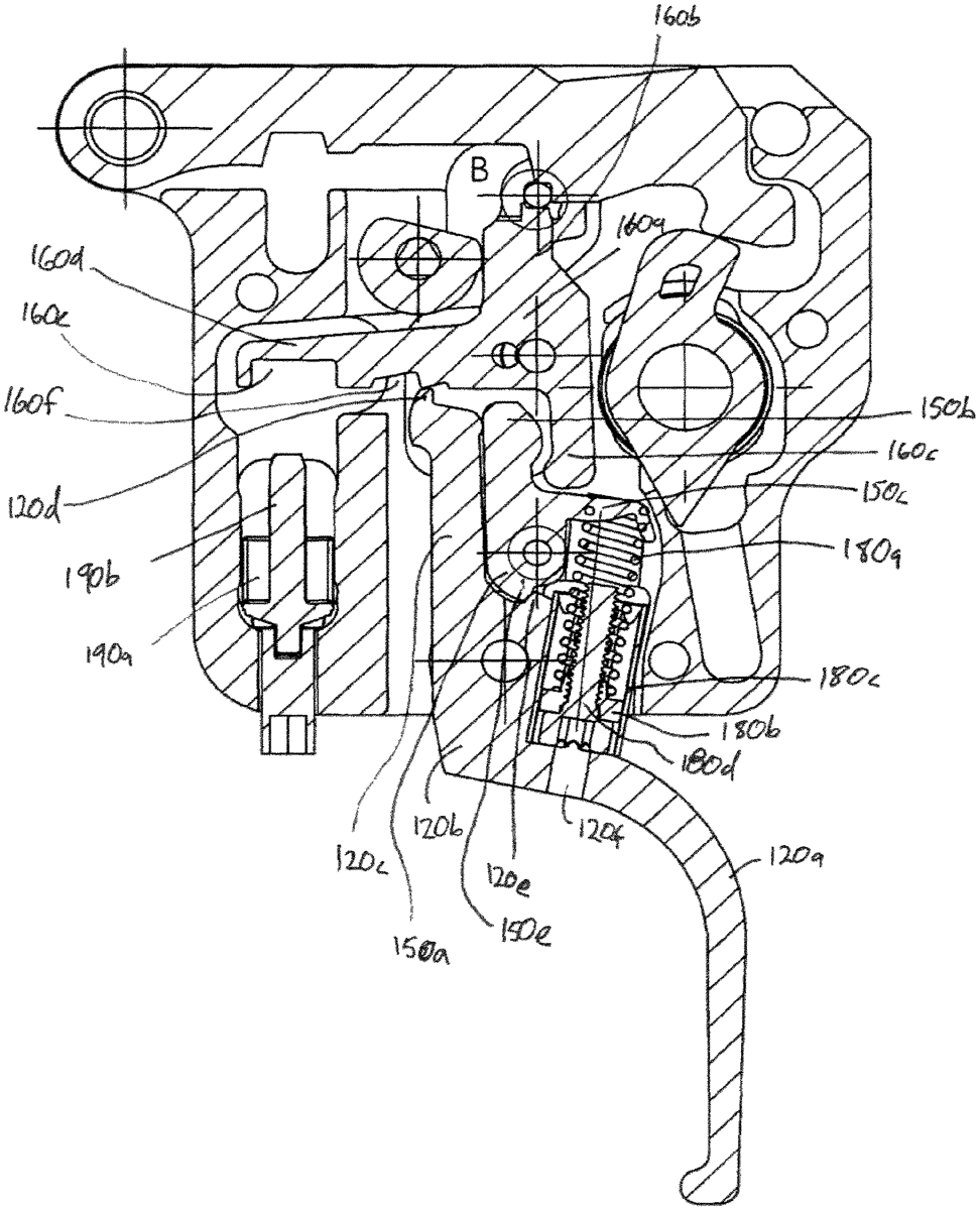
Provided are a trigger assembly, firearm, and various methods and components. An example assembly includes a lower trigger body comprising a trigger lever; a disconnector rotatable relative to the lower trigger body; a trigger tower rotatable relative to the lower trigger body and the disconnector, the trigger tower defining a trigger tower hook; and a hammer defining a hammer sear hook configured to engage the trigger tower hook to hold the hammer in a cocked position. In response to application of a force to the trigger lever, the lower trigger body may rotate and cause the trigger tower to rotate to release the trigger tower hook from the hammer sear hook.
Jul 28, 2026
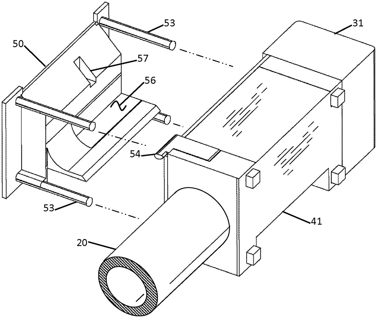
A tool for installing a fire control group in a lower receiver includes a pair of sides. The fire control group includes a set of trigger components and a set of hammer components. The first and second side each have an inner surface and an outer surface, and a recess is formed in each inner surface. When the first and second sides are assembled together, the inner surfaces of the sides contact each other and their recesses cooperate with each other to define a cavity within which the set of trigger components and the set of hammer components are at least partially arranged, the cavity having a bottom opening through which the fire control group may be withdrawn unobstructed by the first and second side. The tool also includes a flexible tie wrapped around the first and second sides for retaining the fire control group in a preloaded state.
Jul 28, 2026
The techniques described herein relate to methods and apparatuses for casing ejection mechanisms. The firearm includes a lever, an adapter with a first hole and second hole, and a magazine inserted inside the first hole. The lever is configured to cause a casing to be ejected in a direction parallel to a plane along which the lever moves while ejecting the casing or at least partially toward a side of the firearm.
Jul 21, 2026
A bolt action firearm has an ejector element movable between a forward position in which a portion of the ejector element protrudes from the bolt face and a rearward position rear of the forward position, an ejector restraint element operable in a restraining position to restrain the ejector element to the rearward position and in a release position to enable movement of the ejector element from the rearward position to the forward position, an actuator movable between a first position and a second position such that seating a cartridge case head in an aligned position motivates the actuator from the first position to the second position, and a linkage connecting the actuator to the ejector restraint element and operable in response to movement of the actuator from the first position to the second position to enable movement of the ejector element from the rearward position to the forward position.
Jul 21, 2026
A base recovery device and a gun equipped with such a device includes a structure extendable between a non-spread out state and a spread out state and having a base-receiving opening delimited by first and second arms parallel to each other, at least one lever which pivots and supports the second arm, and a mechanism for moving the lever. The mechanism includes an actuating member, a drive assembly and a clutch assembly arranged such that at least one lever is automatically moved to an unfolded position, in which the structure is in the spread out state, when the breechblock is moved from closed position to open position during the gun recovery stroke, and such that at least one lever is automatically moved to a folded up position, in which the structure is in the non-spread out state, before the end of the recovery stroke and independently of the breechblock movement.
Jul 21, 2026
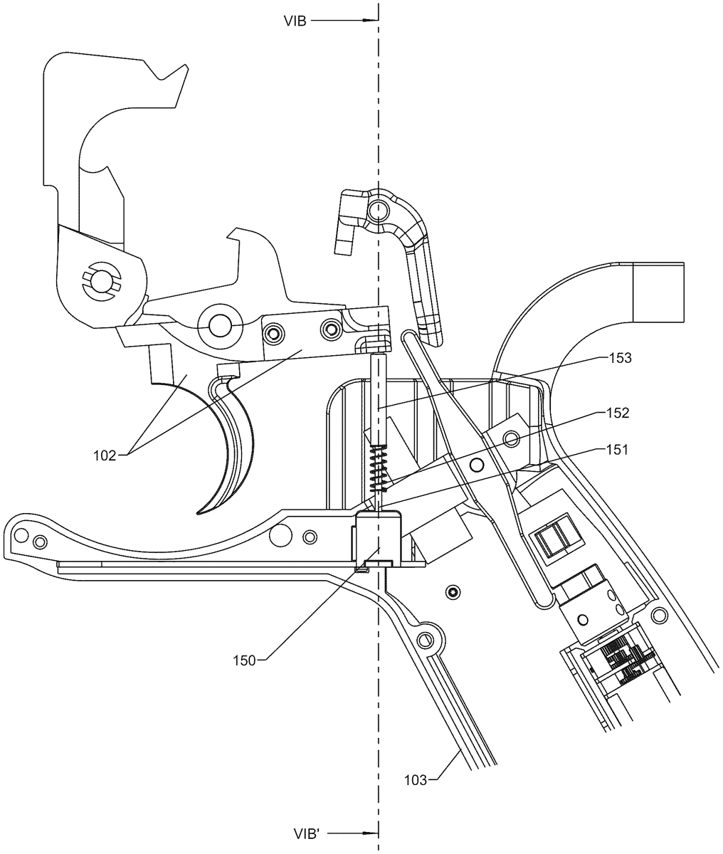
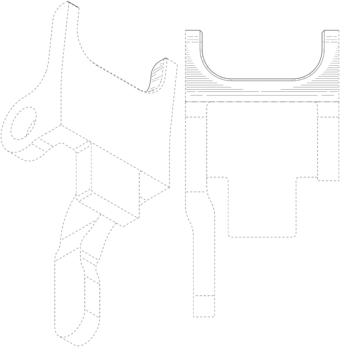
A trigger assembly for a firearm has a frame, a trigger element pivotally connected to the frame and having a trigger lever operable for movement between a forward released position and a rearward actuated position, a hammer pivotally connected to the frame and movable between a cocked position and a striking position, a shroud element pivotally connected to the frame and having a shroud lever operable for movement between a forward disabling position and a rearward enabling position, a link pivotally connected to the frame and having a first portion operably interfacing the reciprocating action element and a second portion operably interfacing the shroud element, and the link being operable when the reciprocating action element moves from the rear recoil position to the forward battery position to motivate the shroud element from the rearward enabling position to the forward disabling position.
Jul 21, 2026
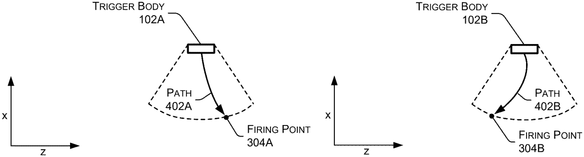
A trigger mechanism that, in various examples, may be configured to pivot or rotate in multiple directions, enabling actuation along multiple axes or planes of motion consistent with natural finger movement. For instance, a trigger may be supported or otherwise connected to a host device—such as a firearm, tool, or other manually actuated mechanism—in a manner that permits movement in multiple directions or rotation about multiple axes, allowing the trigger pull to follow the natural motion path of a user's finger. In some examples, the trigger mechanism may actuate when the trigger reaches one or more defined actuation points or when a threshold level of force is applied—regardless of the trigger's motion path. In this way, the trigger mechanisms of the present disclosure may accommodate the unique trigger pull motions of different users, regardless of hand position, technique, or training level.
Jul 21, 2026
An actuating mechanism including: a base having a helically shaped passage; a movable mass having a helically shaped projection, a first surface of the helically shaped projection mating with a corresponding second surface of the helically shaped passage; and a spring biasing the first surface against the second surface when the base is not being accelerated. Wherein the helically shaped passage, the helically shaped projection and the spring are configured to maintain the helically shaped projection in a first portion of the helically shaped passage upon the base experiencing a first acceleration profile having a first magnitude and a first duration and allow the mass to move to a second portion of the helically shaped passage upon the base experiencing a second acceleration profile having a second acceleration lower than the first acceleration and a second duration greater than the first duration.
Jul 14, 2026
A safing sector for a minigun including a housing with an opening adjacent to barrels of the minigun comprising a safing sector cover; one or more retaining pin assemblies configured to retain the cover to the housing over the opening; a safing sector slide member; a safing sector slide control mechanism including a locking arm configured to impart forward and rearward sliding movement of the safing sector slide member relative to the safing sector cover between at least a fire position and a safe position, and a locking mechanism pivotally coupled to the locking arm and including a shelf stop to engage a locking shelf of the safing sector cover to lock the locking arm and the safing sector slide member in the fire position.
Jul 14, 2026
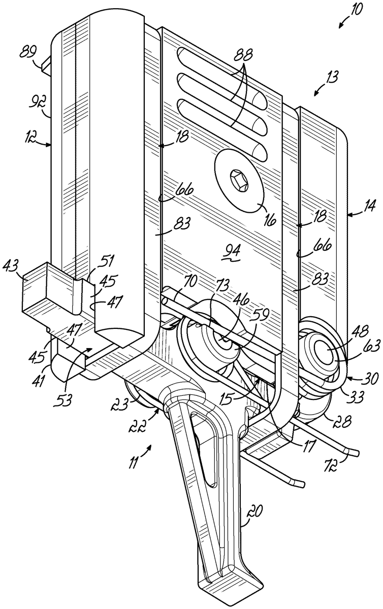
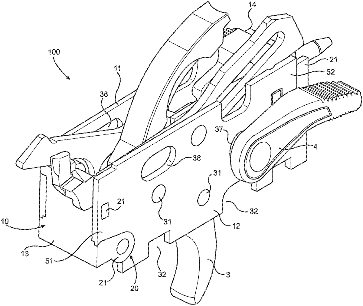
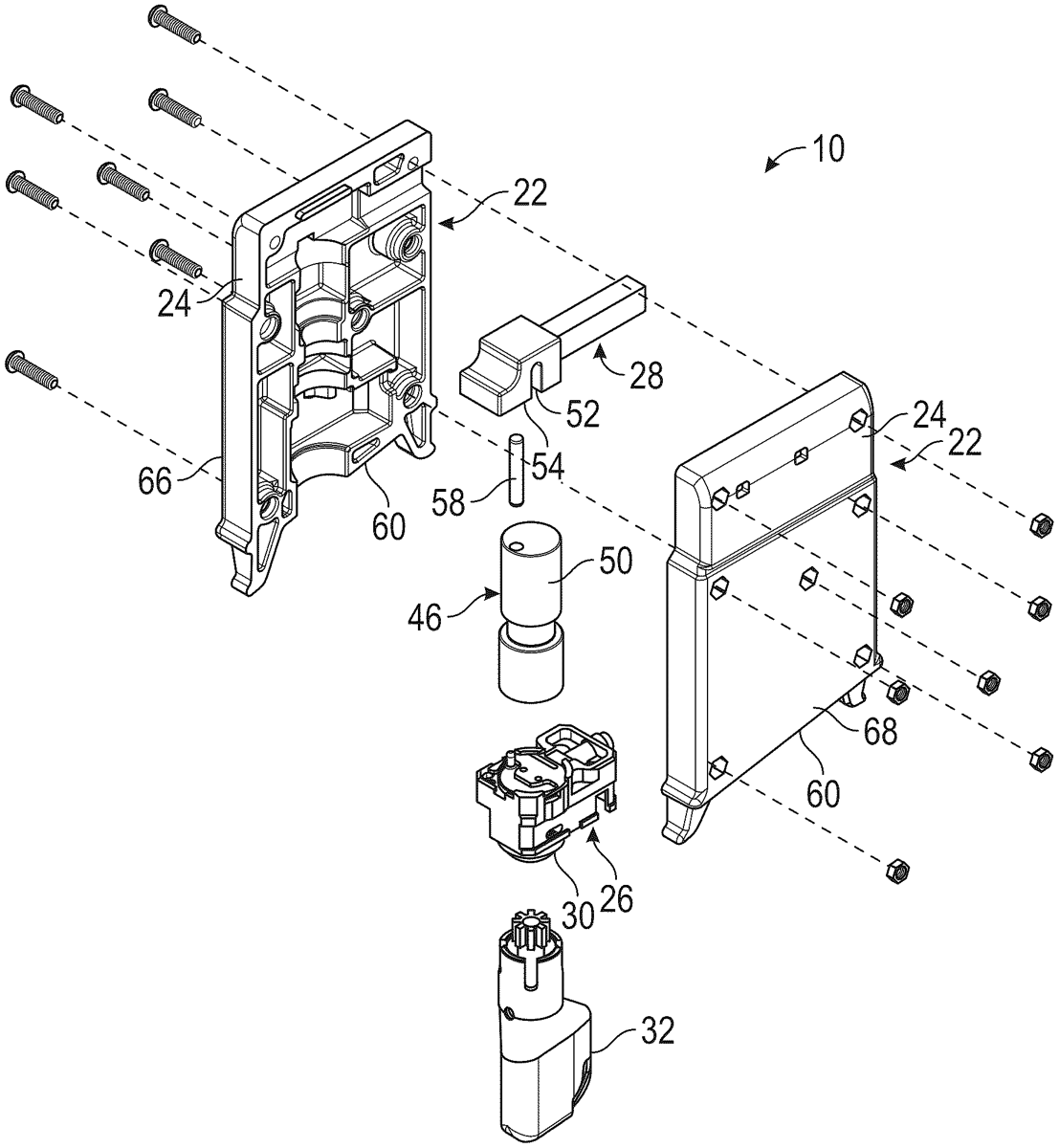
A trigger frame assembly that is received within a grip of a firearm for use in providing a housing for a plurality of internal action component parts of a firearm, such as, a trigger. A trigger frame assembly comprising a plurality of panel members that are braced and connected together via a plurality of mechanical fasteners, or an interlocking snapping mechanism, that allow the panel members to fit firmly together, wherein the mechanical fasteners also allow the panel members to be disassembled, as necessary, thereby allowing for easier replacement and configuration of the panel members and the internal action component parts of the firearm.
Jul 14, 2026
Jul 7, 2026
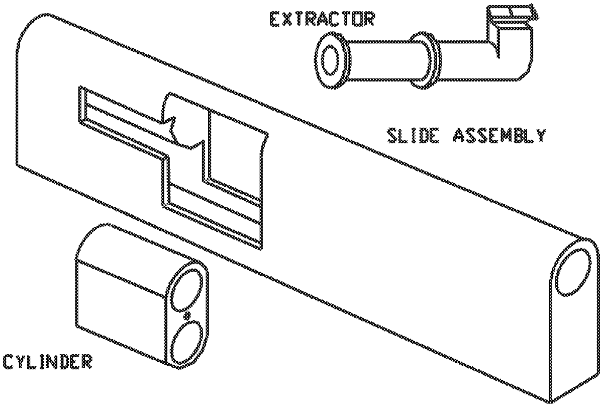
A pistol comprising of a frame, a slide operable to reciprocate with respect to the frame, a barrel connected to the slide, with a cylinder defining a plurality of chambers connected to the slide to reciprocate with the slide, and operable to rotate with respect to the slide. The frame defines an ammunition compartment including an upper most ammunition position. The cylinder has a first chamber registered with the barrel, and a second chamber registered with the upper most ammunition position, such that in response to a cartridge in the first chamber discharging, the slide reciprocates to a recoil position to eject the cartridge case and to cause the upper most cartridge to enter the second chamber. In response to return of the slide to battery, the cylinder rotates to register the second chamber and cartridge, to alignment with the barrel for subsequent discharge.
Jul 7, 2026
An Airsoft shotgun firing mechanism has been developed that fires the spherical projectiles of each shot sequentially in rapid succession. The shotgun firing mechanism directs the airflow sequentially against each spherical projectile in the shot, thus pushing each spherical projectile out of the barrel of the Airsoft shotgun. The flow rates of the air are balanced for all the spherical projectiles so all of the spherical projectiles are accelerating when the last spherical projectile is fired. By balancing the airflows, the spherical projectiles have essentially the same energy. The relative acceleration of the spherical projectiles out of the shotgun barrel is determined or selected by balancing the size and configuration of a bypass channel versus the number or stack of spherical projectiles to be fired.
Jun 23, 2026
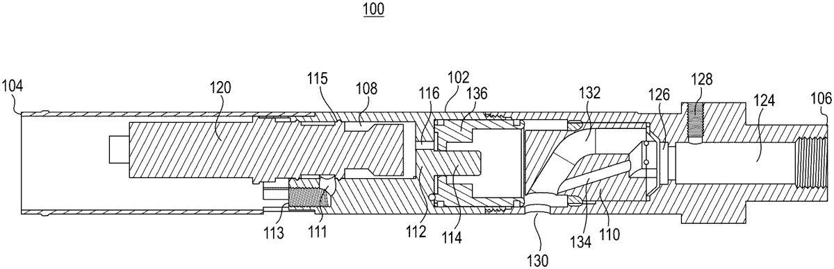
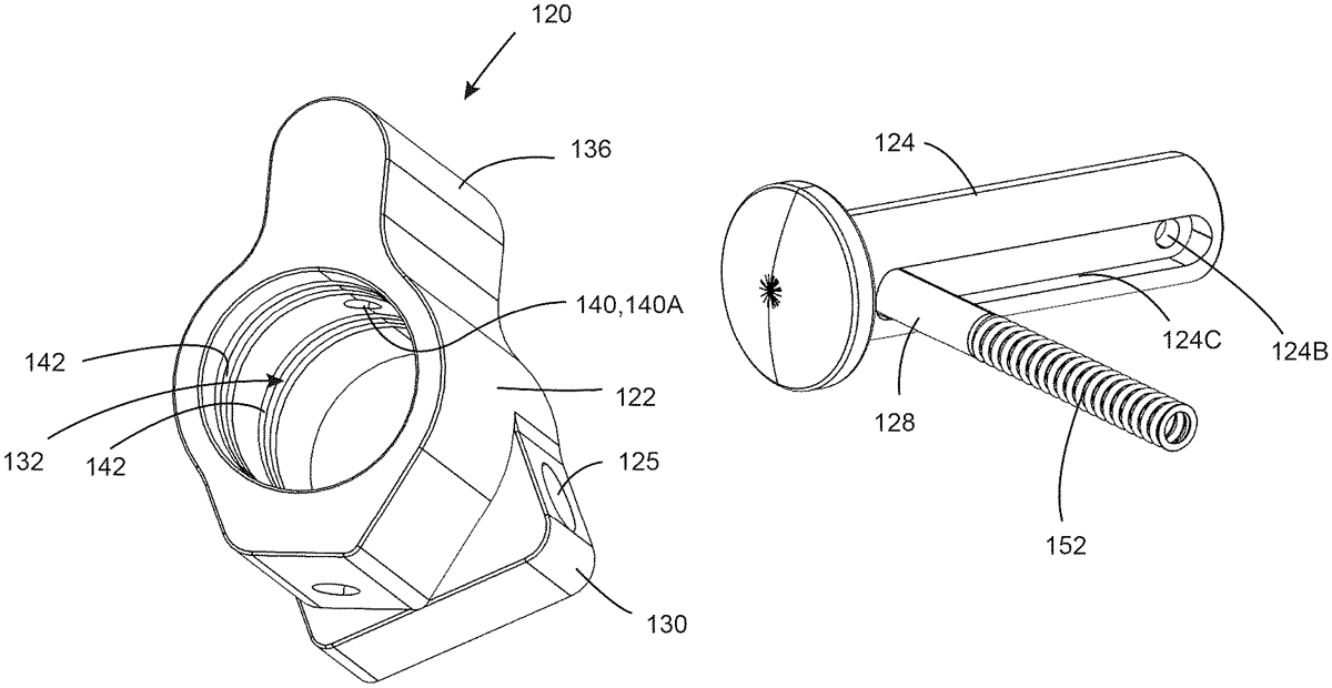
A firearm gas block assembly includes a gas block having a central bore and a retention member passage. The gas block engages a gas block journal of a barrel via the central bore. The retention member passage intersects the central bore to define an opening between the central bore and the retention member passage. A retention member within the retention member passage is moveable between first and second positions. A portion of the retention member extends through the opening when in the first position. No portion of the retention member extends through the opening when in the second position. Gas flow control discontinuities are within a surface of the gas block defining the central passage. A travel limiting member is engaged with the retention member and the gas block for limiting axial movement of the retention member to being between the first and second positions.
Jun 23, 2026
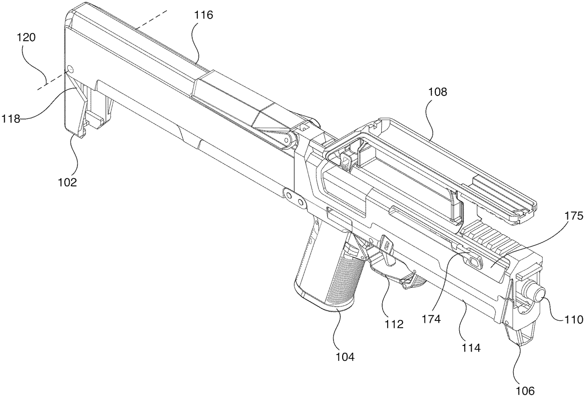
The present disclosure describes a foldable firearm that collapses into a folded state under spring pressure. The foldable firearm may include a foldable grip assembly. The foldable grip assembly may include a foldable pistol grip, a foldable trigger assembly, a folding bar, and a foldable hand stop. The foldable grip assembly may fold into the top shell of the foldable firearm. The foldable firearm may also include an ambidextrous charging handle assembly that may include a bottom portion, a top portion, a guide bar, and two opposing charging handles. The charging handles may be pulled to unfold the foldable firearm, and/or butterflied such that pivoting one charging handle causes the other charging handle to pivot. The first-pivoted charging handle may then be pulled rearwards to unfold the firearm. The first-pivoted charging handle may then be pulled further rearwards to rack the slide of the foldable firearm.
Jun 9, 2026
Locks for a firearm have a lock body configured to be closely and removably received in the magazine well, the lock body having an upper portion configured to extend into the bolt passage when installed in the firearm, with the upper portion interposed between the reciprocating bolt and the forward extending barrel, a locking mechanism at a lower portion of the lock body and having a locked condition and an unlocked condition, and a latch element connected at the upper portion of the lock body and interfacing the locking mechanism to move between an unlocked position when the locking mechanism is in the unlocked condition and a locked position when the locking mechanism is in the locked condition. The latch element may protrude from the lock body when in the locked position. The latch element may protrude in a forward direction from the lock body when in the locked position.
Jun 2, 2026
A trigger reset device includes a trigger block with a front end and a rear end, a hooker and a link trigger pivoted to the trigger block, and a safety switch being displaceably switchable between an open position and a closed position, and further includes a linkage part, a button and a retractor. The button can be operated to allow the linkage part to displace upward, and the retractor can stop and position the linkage part, drive the link trigger to pivot the linkage part, and separate the hooker, in order to achieve a trigger reset function, which makes the operation more convenient and quicker, and also improves the operation efficiency, and the design is simple and easy to operate, which prolongs the service life of the product and reduces the costs of subsequent maintenance and replacement.
May 26, 2026
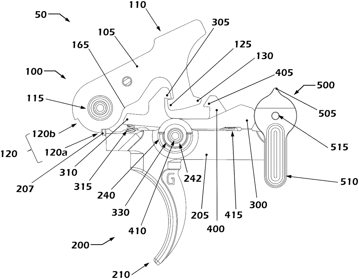
A trigger mechanism that can be used in AR-pattern firearms has a hammer, a trigger member, a disconnector, a locking member, and a “three position” safety selector having safe, standard semi-automatic, and forced reset semi-automatic positions. In the standard semi-automatic position, rearward movement of the bolt carrier causes rearward pivoting of the hammer such that the disconnector hook catches the hammer hook, at which time a user must manually release the trigger member to free the hammer from the disconnector to permit the hammer and trigger member to pivot to the set positions so that the user can pull the trigger member to fire the firearm. In the forced reset semi-automatic position, rearward movement of the bolt carrier causes rearward pivoting of the hammer causing the trigger member to be forced to the set position, the safety selector preventing the disconnector hook from catching the hammer hook, and thereafter when the bolt carrier reaches the substantially in-battery position the user can pull the trigger member to fire the firearm without manually releasing the trigger member. The locking member is pivotable between a first position at which the locking member mechanically blocks the trigger member from moving to the released position and a second position at which the locking member does not mechanically block the trigger member allowing the trigger member to be moved to the released position. The locking member is spring biased toward the first position and moved against the spring bias to the second position by contact from the bolt carrier during forward movement of the bolt carrier as the bolt carrier reaches a substantially in-battery position.
May 19, 2026
A tail for a projectile includes a body having a longitudinal axis. A steering assembly is secured to the body. The steering assembly includes a flap movable from a first position in which the flap does not extend radially beyond the body to a second position in which the flap extends radially beyond the body and at an angle relative to the longitudinal axis, and a flap release mechanism. A projectile including a tail according to the present disclosure is also provided.
May 12, 2026
The present invention concerns a firearm comprising at least one frame; and a barrel group comprising at least one barrel, the barrel group being mounted in a tilting manner with respect to the frame, wherein the frame houses at least one closing device configured to act between the frame and the barrel group so as to selectively prevent the frame of the barrel group from tilting with respect to the frame, and is characterized in that the closing device comprises at least one pair of clamping elements with longitudinal development independent of each other, the clamping elements being slidably housed inside the frame, each along its own longitudinal development axis; and at least one pair of buffers each coupled to a respective clamping element so as to exert an axial thrust force on the respective clamping element substantially in parallel to and/or substantially along the respective longitudinal development axis.
May 12, 2026
A buffer system for a firearm includes a buffer body with an internal passage, a guide rod at least partially disposed in the internal passage such that the guide rod includes a slot, a buffer bumper, an end cap, a magnet attached to the guide rod, and at least one spring. The buffer bumper and the end cap are disposed near a rear end of the guide rod. The magnet creates a force acting on the buffer body.
May 12, 2026
A reloading firearm featuring a mechanism to reduce the blowback of toxic propellant gasses towards the warfighter. The reloading assembly acts in plural segments to increase the firing chamber-closed dwell time, while limiting adverse impact to the overall nominal rate of fire. Greater dwell time corresponds with reduced exposure of the warfighter to propellant gasses. Moreover, increasing the dwell time without otherwise altering the firing cycle has the additional effect of delaying the breech opening after the cartridge is fired. This delay in breech opening permits gas pressure at the muzzle, which may be elevated and/or constrained by flash and/or sound suppression, to dissipate before the breech is opened. Accordingly, when the breech opens later in the firing cycle, there is a reduced pressure gradient across the combination of barrel and firing chamber, which reduces a driving force of propellant gasses towards the warfighter via the open breech.
May 12, 2026
A firearm receiver assembly comprises a receiver body, a top cover, and an ammunition advancing mechanism mounted on the top cover. The top cover is pivotably attached at a mounting portion thereof to a mounting portion of a receiver body for enabling the top cover to be pivotable about a top cover pivot axis between an open position and a closed position with respect to the receiver body. The top cover pivot axis extends parallel to a bore axis of the receiver body.
May 5, 2026
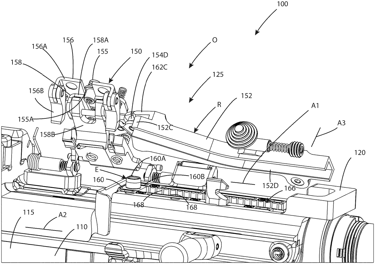
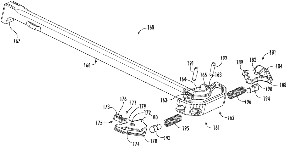
A charging handle assembly for a firearm may include a charging handle body including a handle portion and a shaft portion, a first actuation wing rotatably coupled to the handle portion and configured to rotate about a first rotational axis between a first position and a second position, and a biasing mechanism engaging the first actuation wing and biasing the first actuation wing to the first position. The first actuation wing may include a latch configured to selectively engage an upper receiver assembly of the firearm, and the first actuation wing may have a center of mass disposed along the first rotational axis.
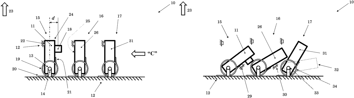
Apr 28, 2026
An inertial mechanical delay mechanism including: a first member rotatable about a first axis in a first direction. The first member having a first center of mass offset from a line parallel to a direction of acceleration and perpendicular from the first axis. A first elastic material exerts a first biasing force to the first member to bias the first member in a second direction. A second member is rotatable about a second axis in a third direction. The second member rotatable in a third direction by at least indirect interaction with the first member when the first member rotates a first angle in the first direction. A second elastic material exerts a second biasing force to the second member to bias the second member in a fourth direction. The first member is configured to rotate the first angle when the acceleration is greater than a predetermined magnitude and duration.
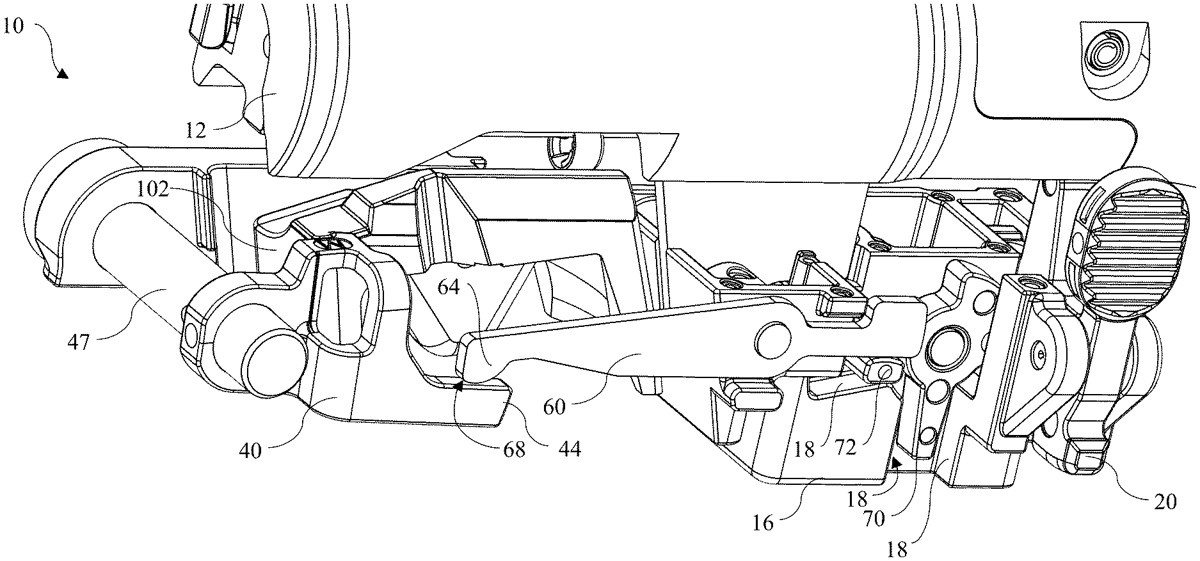
Apr 21, 2026
An assembly for holding a bolt of a firearm in an open position is disclosed. The assembly comprises a bolt catch pivotable about a first axis toward and away from a catching position. In the catching position, a portion of the bolt catch is within a path of travel of the bolt. A follower transfer adapter is pivotable about a second axis. The follower transfer adapter includes an engagement portion that is configured to engage a follower of a magazine. Optionally, the follower transfer adapter includes an overhang lip that extends transversely to the longitudinal axis of the firearm and into a path of travel of the follower to define the engagement portion. The engagement portion is positioned between the second axis and the bolt catch along the longitudinal axis of the firearm. A linkage transfers rotational movement of the follower transfer adapter to rotation of the bolt catch.
Apr 21, 2026
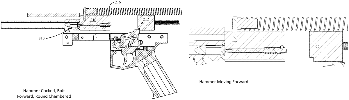
A firearm which provides recoil reduction using the kinetic energy of the hammer to cancel a portion of the bolt's recoil after a round has been fired. After the bolt starts to move rearward in response to the detonation, the hammer's forward kinetic energy is transferred onto the bolt by striking it at the moment the bolt starts to travel rearward or after the bolt has started its rearward motion.
Apr 7, 2026
Braking mechanism for a gun includes a fork whose arms are abutted by supporting pins that abut on brake rollers. A breech that has vertical engagement grooves. Spring-loaded pins with compression springs are arranged against supporting pins. The body of the fork is terminated by a tapered tongue extending into a cavity which follows the fork. Behind the tongue a rod is arranged, which passes into the cavity in a sleeve. The sleeve is provided at one end with an end rod, which is provided at its face with a cylindrical ending arranged eccentrically below its center. The supporting pin is provided with a vertical elongated groove to accommodate the safety pin. In front of the trigger a locking lever of the control arm is placed. At the end is the control arm provided with a transverse beam, which is accommodated above the ending of the end rod.
Apr 7, 2026
A firearm with ambidextrous bolt release mechanism includes a barrel and a bolt slideably mounted in the receiver for axial movement between forward closed breech position in battery with the barrel and a rearward open breech position. A recoil spring biases the bolt forward. A side-mounted bolt catch lever is configured and operable to selectively hold the bolt in the open breech position, and disengage the bolt to reclose the breech when manually actuated. A transversely movable actuator plunger allows a user to release the bolt from the side of the firearm opposite the bolt catch lever side. The plunger comprises an inclined camming surface which slideably engages a mating inclined camming ramp on the lever. Wedging action applied to the bolt catch lever by the plunger rotates the lever about its pivot axis to disengage and release the bolt.
Mar 31, 2026
A firearm has a magazine disconnect mechanism. The firearm includes a trigger operable between a resting position and a pulled position. The magazine disconnect mechanism has a trigger block positioned between the trigger and a magazine well of the firearm, where the trigger block is movable between a blocking position and a non-blocking position. In the blocking position the trigger block obstructs moving the trigger to the pulled position. The trigger block occupies the non-blocking position when a magazine is installed in the magazine well, and the trigger block occupies the blocking position when the magazine is absent from the magazine well.
Mar 31, 2026
An archery bow is disclosed. Bows of the present disclosure comprise lever cams. The lever cam includes a base and an elongated lever arm that extends upwards or downwards, depending on which end of the bow the lever cam is attached to. The lever cams are rotatably secured between the split limbs of the bow. In some embodiments, the bows include an adjustment screw to change the position of an offset axle relative to a lever axle. In other embodiments, the bows include a pair of adjustable bowstring modules attachable to the respective elongated lever arms to alter the draw length of the bowstring.
Mar 24, 2026
A firearm operating system includes a forward bolt with an internal cavity, a carrier disposed on a rear side of the forward bolt where the carrier includes a cavity, a short cam pin, a plurality of bearings, a retracted configuration, and a deployed configuration. At least a portion of a forward section of the short cam pin is disposed within the internal cavity of the forward bolt. At least a portion of a rear section of the short cam pin is disposed within the cavity of the carrier. Movement from the retracted configuration to the deployed configuration includes movement in a forward/aft direction of the short cam pin relative to the forward bolt and movement of the plurality of bearings.
Mar 17, 2026
An automatic firearm is provided, which operates with a system which unlocks the rifle with a certain force and makes it ready for firing again by using this energy, while the mechanism accelerates backwards with the force created by the pressure formed in the barrel after the weapon is fired, and the idle parts in the mechanism move forward due to inertia, creating create kinetic energy and includes apparatus suitable for this system.
Mar 17, 2026
A trigger mechanism that can be used in AR-pattern firearms has a hammer, a trigger member, a disconnector, a cam, and a “three position” safety selector having safe, standard semi-automatic, and forced reset semi-automatic positions. In the standard semi-automatic position, rearward movement of the bolt carrier causes rearward pivoting of the hammer and pivoting of the cam from a first position to a second position such that a cam lobe forces the trigger member towards the set position, but prior to reaching the set position the disconnector hook catches the hammer hook, at which time a user must manually release the trigger member to free the hammer from the disconnector to permit the hammer and trigger member to pivot to their set positions so that the user can pull the trigger member to fire the firearm. In the forced reset semi-automatic position, rearward movement of the bolt carrier causes rearward pivoting of the hammer and pivoting of the cam from the first position to the second position such that the cam lobe forces the trigger member to the set position, the safety selector preventing the disconnector hook from catching the hammer hook, at which time the user can pull the trigger member to fire the firearm without manually releasing the trigger member.