US12753987 - Crossbow with cam assembly
The patent describes a crossbow featuring a cam assembly that allows for the vertical displacement of a power cable away from the plane of rotation as the drawstring is drawn, creating a gap for smooth operation. This design includes a string carrier and a retaining mechanism that work together to securely engage and release the drawstring during use.
Claim 1
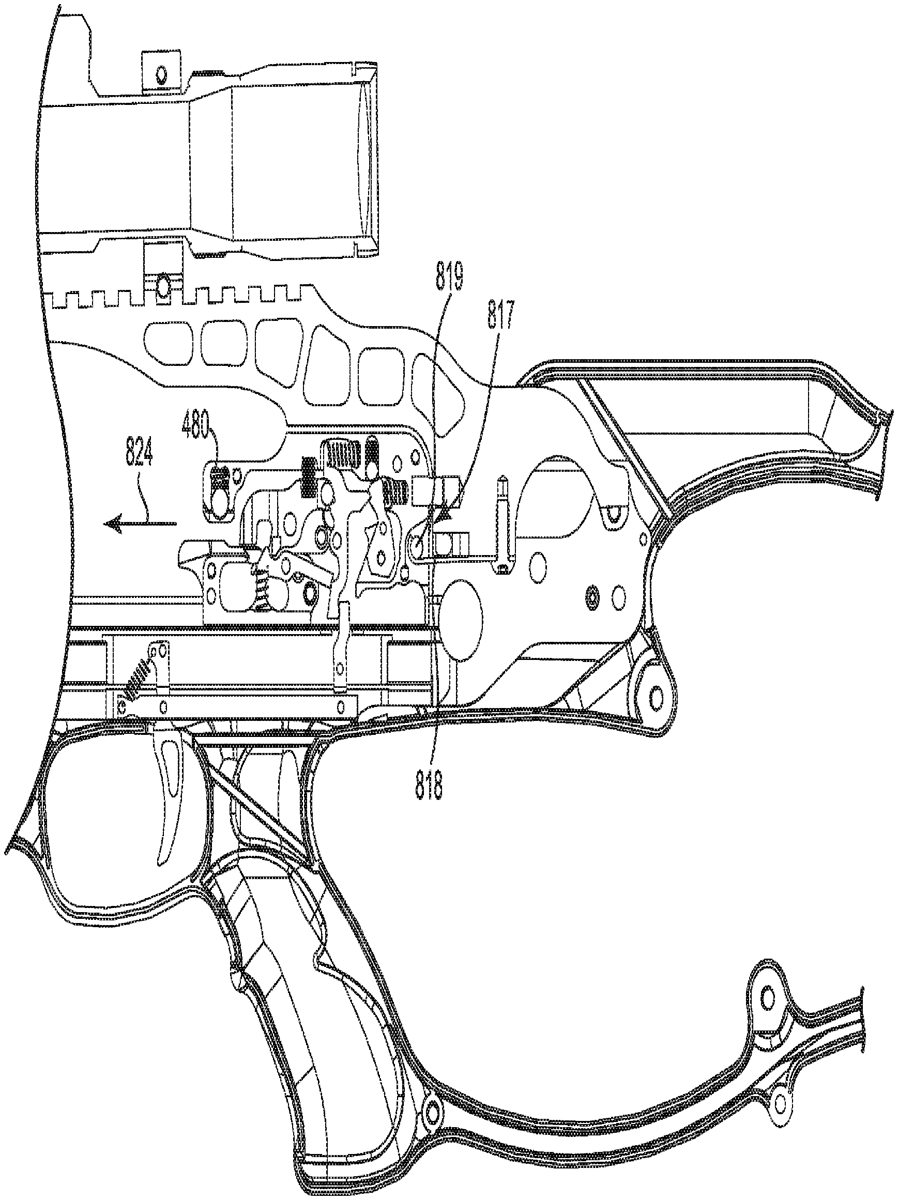
1 . A crossbow comprising: a center rail; a riser coupled with the center rail; a limb coupled to the riser; a drawstring configured to move between a released configuration and a drawn configuration; a string carrier slidably coupled with the center rail, the string carrier including a pin and a string catch configured to selectively engage the drawstring, the string carrier configured to move between a forward position and a retracted position; a retaining mechanism movably coupled with the center rail and configured to selectively engage with the pin of the string carrier to selectively retain the string carrier in the retracted position, wherein the retaining mechanism moves between a first position in which the retaining mechanism is engaged with the pin and a second position in which the retaining mechanism is disengaged from the pin, and wherein the retaining mechanism is positioned rearward of the string catch; a release lever coupled with the retaining mechanism and actuatable to move the retaining mechanism between the first position and the second position, wherein an engagement between the retaining mechanism in the first position with the pin of the string carrier in the retracted position substantially prevents an actuation of the release lever to move the retaining mechanism to the second position, and wherein the string carrier is movable to a disengage position rearward of the retracted position to disengage the pin from the retaining mechanism such that, when the string carrier is in the disengage position, an actuation of the release lever moves the retaining mechanism from the first position to the second position; a power cable including an end portion and a second portion; and a cam assembly rotatably coupled to the limb about an axis of rotation, the cam assembly including: a string guide defining a plane of rotation of the cam assembly about the axis of rotation and structured to support the drawstring; a drawstring attachment post structured to secure the drawstring to the string guide; a power cable journal extending vertically away from the plane of rotation along the axis of rotation, the power cable journal structured to support the power cable; and a power cable attachment post structured to secure the end portion of the power cable to the string guide, the power cable attachment post extending vertically from the string guide to position the end portion of the power cable a first distance from the plane of rotation; and wherein, during operation of the crossbow as the drawstring moves from the released configuration to the drawn configuration, the power cable journal displaces the second portion of the power cable vertically away from the plane of rotation such that the second portion of the power cable is positioned a second distance from the plane of rotation with the drawstring in the drawn configuration, wherein the second distance is greater than the first distance, wherein the vertical displacement of the second portion of the power cable creates a gap between the second portion of the power cable and the plane of rotation; wherein, during operation of the crossbow as the drawstring moves from the released configuration to the drawn configuration, (i) the string guide rotates about the axis of rotation and (ii) the drawstring attachment post, the power cable attachment post, and the end portion of the power cable pass within the gap between the second portion of the power cable and the plane of rotation without contacting the second portion of the power cable. a center rail; a riser coupled with the center rail; a limb coupled to the riser; a drawstring configured to move between a released configuration and a drawn configuration; a string carrier slidably coupled with the center rail, the string carrier including a pin and a string catch configured to selectively engage the drawstring, the string carrier configured to move between a forward position and a retracted position; a retaining mechanism movably coupled with the center rail and configured to selectively engage with the pin of the string carrier to selectively retain the string carrier in the retracted position, wherein the retaining mechanism moves between a first position in which the retaining mechanism is engaged with the pin and a second position in which the retaining mechanism is disengaged from the pin, and wherein the retaining mechanism is positioned rearward of the string catch; a release lever coupled with the retaining mechanism and actuatable to move the retaining mechanism between the first position and the second position, wherein an engagement between the retaining mechanism in the first position with the pin of the string carrier in the retracted position substantially prevents an actuation of the release lever to move the retaining mechanism to the second position, and wherein the string carrier is movable to a disengage position rearward of the retracted position to disengage the pin from the retaining mechanism such that, when the string carrier is in the disengage position, an actuation of the release lever moves the retaining mechanism from the first position to the second position; a power cable including an end portion and a second portion; and a cam assembly rotatably coupled to the limb about an axis of rotation, the cam assembly including: a string guide defining a plane of rotation of the cam assembly about the axis of rotation and structured to support the drawstring; a drawstring attachment post structured to secure the drawstring to the string guide; a power cable journal extending vertically away from the plane of rotation along the axis of rotation, the power cable journal structured to support the power cable; and a power cable attachment post structured to secure the end portion of the power cable to the string guide, the power cable attachment post extending vertically from the string guide to position the end portion of the power cable a first distance from the plane of rotation; and a string guide defining a plane of rotation of the cam assembly about the axis of rotation and structured to support the drawstring; a drawstring attachment post structured to secure the drawstring to the string guide; a power cable journal extending vertically away from the plane of rotation along the axis of rotation, the power cable journal structured to support the power cable; and a power cable attachment post structured to secure the end portion of the power cable to the string guide, the power cable attachment post extending vertically from the string guide to position the end portion of the power cable a first distance from the plane of rotation; and wherein, during operation of the crossbow as the drawstring moves from the released configuration to the drawn configuration, the power cable journal displaces the second portion of the power cable vertically away from the plane of rotation such that the second portion of the power cable is positioned a second distance from the plane of rotation with the drawstring in the drawn configuration, wherein the second distance is greater than the first distance, wherein the vertical displacement of the second portion of the power cable creates a gap between the second portion of the power cable and the plane of rotation; wherein, during operation of the crossbow as the drawstring moves from the released configuration to the drawn configuration, (i) the string guide rotates about the axis of rotation and (ii) the drawstring attachment post, the power cable attachment post, and the end portion of the power cable pass within the gap between the second portion of the power cable and the plane of rotation without contacting the second portion of the power cable.
Google Patents
https://patents.google.com/patent/US12753987
USPTO PDF
https://image-ppubs.uspto.gov/dirsearch-public/print/downloadPdf/12753987