US12760980 - Skipless trigger systems and methods
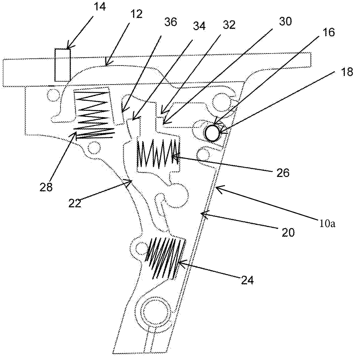
The patent describes a skipless trigger assembly designed for sliding weapons, which incorporates a series of spring-loaded components to ensure that the weapon does not fire automatically. This assembly features distinct positions that control the firing pin’s movement, preventing accidental discharge while allowing for intentional firing when the trigger is pulled.
Claim 1
1 . A trigger assembly for a weapon comprising: a trigger housing; a pivot arm configured to be pushed by a first spring toward a side of the trigger housing facing a front side of the weapon, wherein the pivot arm has a first protrusion; a disconnector coupled to the pivot arm, wherein the disconnector includes a second protrusion that is configured to be pushed away from the pivot arm by a second spring; a firing pin release configured to be pushed by a third spring toward a top side of the trigger housing, wherein the firing pin release has a third protrusion and a fourth protrusion; a pin coupled to the pivot arm; a trigger coupled via a linkage to the pin and configured to be pulled to cause the pin to be moved away from the front side of the weapon; and a firing pin, wherein the trigger assembly is configured to have: (1) a first position before the trigger has been pulled, in which the first protrusion is wedged against the third protrusion, thereby causing the firing pin release to prevent the firing pin from sliding to fire the weapon; (2) a second position after the trigger has been pulled, in which the first protrusion is no longer wedged against the third protrusion and the firing pin release has pivoted away from the top side of the trigger housing to allow the firing pin to fire the weapon; and (3) a third position after the trigger has been pulled to fire the weapon and before the trigger has been released, in which the firing pin has recoiled and the second protrusion is wedged against the fourth protrusion, thereby causing the firing pin release to prevent the firing pin from sliding to fire the weapon. a trigger housing; a pivot arm configured to be pushed by a first spring toward a side of the trigger housing facing a front side of the weapon, wherein the pivot arm has a first protrusion; a disconnector coupled to the pivot arm, wherein the disconnector includes a second protrusion that is configured to be pushed away from the pivot arm by a second spring; a firing pin release configured to be pushed by a third spring toward a top side of the trigger housing, wherein the firing pin release has a third protrusion and a fourth protrusion; a pin coupled to the pivot arm; a trigger coupled via a linkage to the pin and configured to be pulled to cause the pin to be moved away from the front side of the weapon; and a firing pin, wherein the trigger assembly is configured to have: (1) a first position before the trigger has been pulled, in which the first protrusion is wedged against the third protrusion, thereby causing the firing pin release to prevent the firing pin from sliding to fire the weapon; (2) a second position after the trigger has been pulled, in which the first protrusion is no longer wedged against the third protrusion and the firing pin release has pivoted away from the top side of the trigger housing to allow the firing pin to fire the weapon; and (3) a third position after the trigger has been pulled to fire the weapon and before the trigger has been released, in which the firing pin has recoiled and the second protrusion is wedged against the fourth protrusion, thereby causing the firing pin release to prevent the firing pin from sliding to fire the weapon.
Google Patents
https://patents.google.com/patent/US12760980
USPTO PDF
https://image-ppubs.uspto.gov/dirsearch-public/print/downloadPdf/12760980