US12723834 - Training firearm
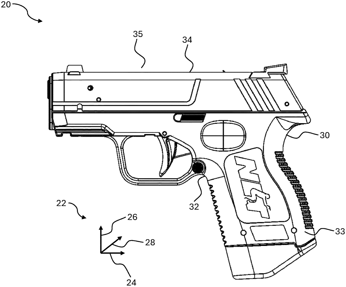
The invention describes a training firearm designed to replicate the trigger mechanism of real firearms, incorporating components such as a break arm, movable magnet, reed switch, and shot indicator to simulate firing with a laser. The mechanism activates the shot indicator when the trigger is pulled, allowing for realistic training experiences without using live ammunition.
Claim 1
1 . A training firearm, comprising: a frame having a grip portion and an upper portion; a break arm movably attached within the frame, the break arm having a movable magnet attached thereto and operatively configured to move with respect to the frame, the break arm having a rest position and an operating position with respect to the frame; a frame magnet attached to the frame and aligned having similar polarity to the movable magnet so as to have an attraction there between, the break arm having the rest position with respect to the frame whereby force is required to separate the movable magnet from the frame magnet; a trigger movably attached to the frame and operatively configured to displace in a longitudinally rearward direction, the trigger having a resting position when the trigger is in a longitudinally forward position with respect to the frame; a reed switch fixedly attached to the frame whereby the reed switch is operatively configured to have a switch sensitivity field where magnetic disturbance within the switch sensitivity field activates the reed switch; a shot indicator in electrical communication with the reed switch, and a power source whereby the shot indicator is configured to turn on and draw voltage from the power source through the reed switch when the reed switch is activated; wherein the movable magnet of the break arm is operatively configured to reposition in the frame to place the magnetic field of the movable magnet within the switch sensitivity field whereby activating the reed switch as the break arm repositions from the rest position to the operating position, wherein, the break arm repositions from the rest position to the operating position by way of longitude rearward motion of the trigger which repositions the break arm so the movable magnet is at a distance from the frame magnet greater than when the break arm is in the rest position, and wherein, as the movable magnet separates from the frame magnet, thereby enabling a non-linear drop in force with respect to the distance between the movable magnet and the frame magnet or by causing lower force to continue rearward force past the rest position of the trigger and further the movable magnet carries inertia from repositioning of the trigger in the longitudinally rearward direction to reposition the movable magnet within the switch sensitivity field of the reed switch, whereby activating the reed switch to supply voltage from the power source to the shot indicator. a frame having a grip portion and an upper portion; a break arm movably attached within the frame, the break arm having a movable magnet attached thereto and operatively configured to move with respect to the frame, the break arm having a rest position and an operating position with respect to the frame; a frame magnet attached to the frame and aligned having similar polarity to the movable magnet so as to have an attraction there between, the break arm having the rest position with respect to the frame whereby force is required to separate the movable magnet from the frame magnet; a trigger movably attached to the frame and operatively configured to displace in a longitudinally rearward direction, the trigger having a resting position when the trigger is in a longitudinally forward position with respect to the frame; a reed switch fixedly attached to the frame whereby the reed switch is operatively configured to have a switch sensitivity field where magnetic disturbance within the switch sensitivity field activates the reed switch; a shot indicator in electrical communication with the reed switch, and a power source whereby the shot indicator is configured to turn on and draw voltage from the power source through the reed switch when the reed switch is activated; wherein the movable magnet of the break arm is operatively configured to reposition in the frame to place the magnetic field of the movable magnet within the switch sensitivity field whereby activating the reed switch as the break arm repositions from the rest position to the operating position, wherein, the break arm repositions from the rest position to the operating position by way of longitude rearward motion of the trigger which repositions the break arm so the movable magnet is at a distance from the frame magnet greater than when the break arm is in the rest position, and wherein, as the movable magnet separates from the frame magnet, thereby enabling a non-linear drop in force with respect to the distance between the movable magnet and the frame magnet or by causing lower force to continue rearward force past the rest position of the trigger and further the movable magnet carries inertia from repositioning of the trigger in the longitudinally rearward direction to reposition the movable magnet within the switch sensitivity field of the reed switch, whereby activating the reed switch to supply voltage from the power source to the shot indicator.
Google Patents
https://patents.google.com/patent/US12723834
USPTO PDF
https://image-ppubs.uspto.gov/dirsearch-public/print/downloadPdf/12723834