US12760979 - Modular firearm trigger system
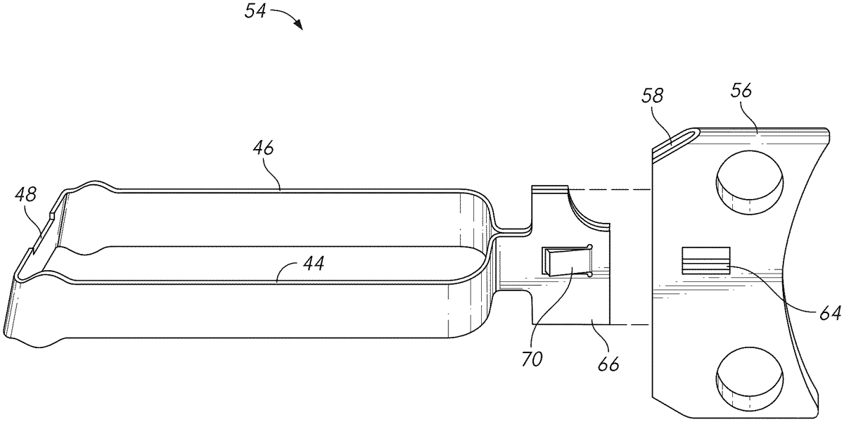
The patent describes a modular trigger system for pistols that allows users to easily detach and replace the trigger shoe without removing the trigger bow from the frame. This system includes a selectable detachment feature that utilizes a resilient snap protrusion to secure the trigger shoe to the trigger bow.
Claim 1
1 . A pistol, comprising: (a) a frame, having a forward end and a rearward end; (b) said frame including a grip and a magazine well; (c) said frame including a left channel running along a left side of said magazine well, said left channel being open in the rear and closed in the front; (d) said frame including a right channel running along a right side of said magazine well, said left channel being open in the rear and closed in the front, (e) a trigger guard enclosing a trigger area; (f) a firing mechanism; (g) a trigger bow, including, (i) a right side rail, (ii) a left side rail, (iii) a cross-bar connecting a rear portion of said right side rail to a rear portion of said left side rail, (iv) a neck connecting a front portion of said right side rail to a front portion of a left side rail, (v) a tang protruding forward from said neck; (h) said trigger bow slidably received within said frame with said right side rail resting in said right channel, said left side rail resting in said left channel, and said cross-bar lying proximate said firing mechanism; (i) said tang of said trigger bow extending into said trigger area: (j) a trigger shoe attached to said trigger bow; (k) a selectable detachment feature selectively attaching said trigger shoe to said trigger bow; (l) wherein said selectable detachment feature comprises: an opening in said trigger shoe; and a resilient snap protrusion extending laterally from said tang and into said opening in said trigger shoe. (a) a frame, having a forward end and a rearward end; (b) said frame including a grip and a magazine well; (c) said frame including a left channel running along a left side of said magazine well, said left channel being open in the rear and closed in the front; (d) said frame including a right channel running along a right side of said magazine well, said left channel being open in the rear and closed in the front, (e) a trigger guard enclosing a trigger area; (f) a firing mechanism; (g) a trigger bow, including, (i) a right side rail, (ii) a left side rail, (iii) a cross-bar connecting a rear portion of said right side rail to a rear portion of said left side rail, (iv) a neck connecting a front portion of said right side rail to a front portion of a left side rail, (v) a tang protruding forward from said neck; (i) a right side rail, (ii) a left side rail, (iii) a cross-bar connecting a rear portion of said right side rail to a rear portion of said left side rail, (iv) a neck connecting a front portion of said right side rail to a front portion of a left side rail, (v) a tang protruding forward from said neck; (h) said trigger bow slidably received within said frame with said right side rail resting in said right channel, said left side rail resting in said left channel, and said cross-bar lying proximate said firing mechanism; (i) said tang of said trigger bow extending into said trigger area: (j) a trigger shoe attached to said trigger bow; (k) a selectable detachment feature selectively attaching said trigger shoe to said trigger bow; (l) wherein said selectable detachment feature comprises: an opening in said trigger shoe; and a resilient snap protrusion extending laterally from said tang and into said opening in said trigger shoe. an opening in said trigger shoe; and a resilient snap protrusion extending laterally from said tang and into said opening in said trigger shoe.
Google Patents
https://patents.google.com/patent/US12760979
USPTO PDF
https://image-ppubs.uspto.gov/dirsearch-public/print/downloadPdf/12760979