US12607429 - Bow attachment weight rest
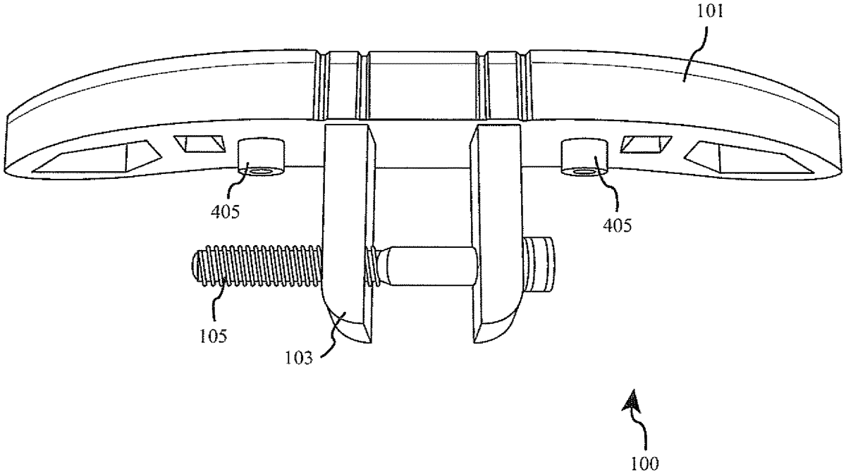
The patent describes a weight support apparatus designed for attachment to an archery bow, featuring a base with lateral wings and adjustable arms that secure the bow in place. This apparatus utilizes a through bolt mechanism to ensure stability and ease of attachment, allowing for a customizable fit on various bow models.
Claim 1
1 . A weight support apparatus for attachment to an archery bow, the apparatus comprising: a. a base comprising two wings, said wings extending laterally away from a centerline of the base; b. two or more arms comprising: i. a shoe; ii. a shoe slot arranged in the middle of said shoe; iii. a lug portion arranged perpendicular to the shoe and extending out and way from a medial face of the shoe, and iv. one or more bolt holes arranged in the middle of said lug portion; wherein, the two or more arms are joined by a through bolt extending through the one or more bolt holes; c. a base channel configured to receive the shoes of said arms; and d. a channel slot arranged at the bottom of the base channel configured to join the two or more arms to the base, wherein, the arms are positioned opposing one another in the channel slot and are slidably attached to the base by a through bolt extending through the shoe slot and channel slot. a. a base comprising two wings, said wings extending laterally away from a centerline of the base; b. two or more arms comprising: i. a shoe; ii. a shoe slot arranged in the middle of said shoe; iii. a lug portion arranged perpendicular to the shoe and extending out and way from a medial face of the shoe, and iv. one or more bolt holes arranged in the middle of said lug portion; wherein, the two or more arms are joined by a through bolt extending through the one or more bolt holes; i. a shoe; ii. a shoe slot arranged in the middle of said shoe; iii. a lug portion arranged perpendicular to the shoe and extending out and way from a medial face of the shoe, and iv. one or more bolt holes arranged in the middle of said lug portion; wherein, the two or more arms are joined by a through bolt extending through the one or more bolt holes; wherein, the two or more arms are joined by a through bolt extending through the one or more bolt holes; c. a base channel configured to receive the shoes of said arms; and d. a channel slot arranged at the bottom of the base channel configured to join the two or more arms to the base, wherein, the arms are positioned opposing one another in the channel slot and are slidably attached to the base by a through bolt extending through the shoe slot and channel slot.
Google Patents
https://patents.google.com/patent/US12607429
USPTO PDF
https://image-ppubs.uspto.gov/dirsearch-public/print/downloadPdf/12607429