US12768619 - Riflescope or other optical device with pivotable system erector
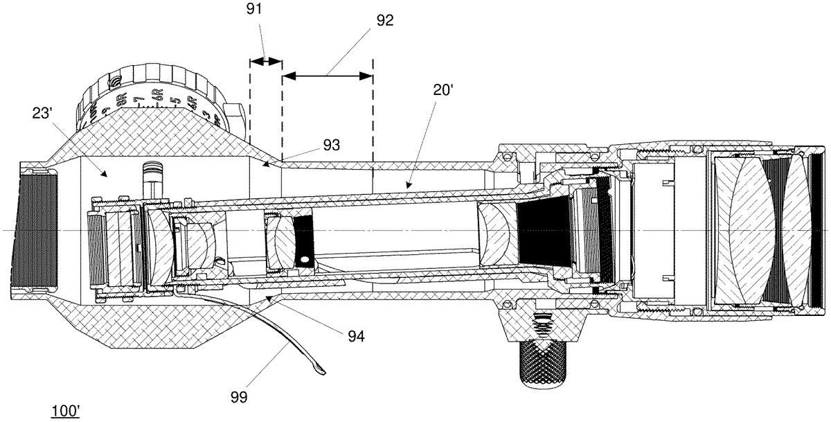
The patent describes a riflescope featuring a pivotable system erector housed within a main tube with a diameter of less than thirty-five millimeters, allowing for precise optical adjustments. The design includes an adjustment turret that enables movement of the system erector along a defined path, facilitating maximum angles of declination and inclination for enhanced targeting accuracy.
Claim 1
1 . A riflescope or another optical device, comprising: a main tube to house a pivotable system erector, the pivotable system erector containing one or more lenses or other optical elements; an adjustment turret including an adjustment member, the adjustment member in contact with a first end of the pivotable system erector, the adjustment turret and its adjustment member operable to pivot the pivotable system erector about a pivot point associated with a second opposite end of the pivotable system erector, to move at least part of the first end along a path of movement through an interior of the main tube, the path of movement including at least a first point corresponding to a maximum angle of declination of the pivotable system erector, a second point corresponding to a maximum angle of inclination of the pivotable system erector, and a third point corresponding to no inclination, and no declination, of the pivotable system erector; the main tube to house the pivotable system erector, characterized in that 1) is has a main tube mounting diameter of less than thirty five millimeters, 2) a total distance from the first point to the second point is not greater than six times a reach of the portion of the adjustment member into the interior of the main tube when the pivotable system erector is coincident with the third point, and 3) an interior of the main tube includes: a cavity section at least partially defining at least one cavity, and an additional section located rearwardly of the cavity section; wherein the path of movement terminates at one end in a cavity of the at least one cavity, wherein a distance from the first point to the second point is greater than an interior diameter of the additional section of the main tube. a main tube to house a pivotable system erector, the pivotable system erector containing one or more lenses or other optical elements; an adjustment turret including an adjustment member, the adjustment member in contact with a first end of the pivotable system erector, the adjustment turret and its adjustment member operable to pivot the pivotable system erector about a pivot point associated with a second opposite end of the pivotable system erector, to move at least part of the first end along a path of movement through an interior of the main tube, the path of movement including at least a first point corresponding to a maximum angle of declination of the pivotable system erector, a second point corresponding to a maximum angle of inclination of the pivotable system erector, and a third point corresponding to no inclination, and no declination, of the pivotable system erector; the main tube to house the pivotable system erector, characterized in that 1) is has a main tube mounting diameter of less than thirty five millimeters, 2) a total distance from the first point to the second point is not greater than six times a reach of the portion of the adjustment member into the interior of the main tube when the pivotable system erector is coincident with the third point, and 3) an interior of the main tube includes: a cavity section at least partially defining at least one cavity, and an additional section located rearwardly of the cavity section; a cavity section at least partially defining at least one cavity, and an additional section located rearwardly of the cavity section; wherein the path of movement terminates at one end in a cavity of the at least one cavity, wherein a distance from the first point to the second point is greater than an interior diameter of the additional section of the main tube.
Google Patents
https://patents.google.com/patent/US12768619
USPTO PDF
https://image-ppubs.uspto.gov/dirsearch-public/print/downloadPdf/12768619