US12760982 - Firearm suppressor
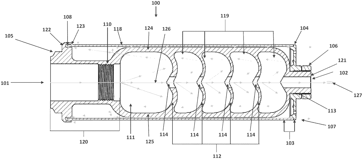
The patent describes a firearm suppressor that features an inner body with a muzzle attachment and multiple baffles, which create a linear projectile path and an expansion chamber. Additionally, an external shroud is designed to cover the inner body and allows propellant gas to exit through a secondary opening, enhancing the suppressor’s functionality.
Claim 1
1 . A suppressor for a firearm defining a distal end and a proximal end, the suppressor comprising: an inner body comprising: a muzzle attachment portion; and a plurality of baffles each defining an opening, wherein the openings of the plurality of baffles collectively define a linear projectile path through the inner body along an axis extending from the proximal end of the suppressor to the distal end of the suppressor defining an exit opening, wherein an expansion chamber is defined between the muzzle attachment portion and one of the plurality of baffles; and an external shroud configured to removably couple to and at least partially cover the inner body, wherein the external shroud is configured to permit at least a portion of propellent gas within the inner body to exit the suppressor via a secondary opening defined between the inner body and the external shroud, wherein the inner body defines a flange that defines a circumferential groove that is configured to receive a proximal end of the external shroud, wherein the flange defines a labyrinth structure configured to define one or more flow directional convolutions between the flange and the external shroud, and wherein the proximal end of the external shroud is inserted into the circumferential groove. an inner body comprising: a muzzle attachment portion; and a plurality of baffles each defining an opening, wherein the openings of the plurality of baffles collectively define a linear projectile path through the inner body along an axis extending from the proximal end of the suppressor to the distal end of the suppressor defining an exit opening, wherein an expansion chamber is defined between the muzzle attachment portion and one of the plurality of baffles; and a muzzle attachment portion; and a plurality of baffles each defining an opening, wherein the openings of the plurality of baffles collectively define a linear projectile path through the inner body along an axis extending from the proximal end of the suppressor to the distal end of the suppressor defining an exit opening, wherein an expansion chamber is defined between the muzzle attachment portion and one of the plurality of baffles; and an external shroud configured to removably couple to and at least partially cover the inner body, wherein the external shroud is configured to permit at least a portion of propellent gas within the inner body to exit the suppressor via a secondary opening defined between the inner body and the external shroud, wherein the inner body defines a flange that defines a circumferential groove that is configured to receive a proximal end of the external shroud, wherein the flange defines a labyrinth structure configured to define one or more flow directional convolutions between the flange and the external shroud, and wherein the proximal end of the external shroud is inserted into the circumferential groove.
Google Patents
https://patents.google.com/patent/US12760982
USPTO PDF
https://image-ppubs.uspto.gov/dirsearch-public/print/downloadPdf/12760982