US12716686 - Vertically adjustable belt loop
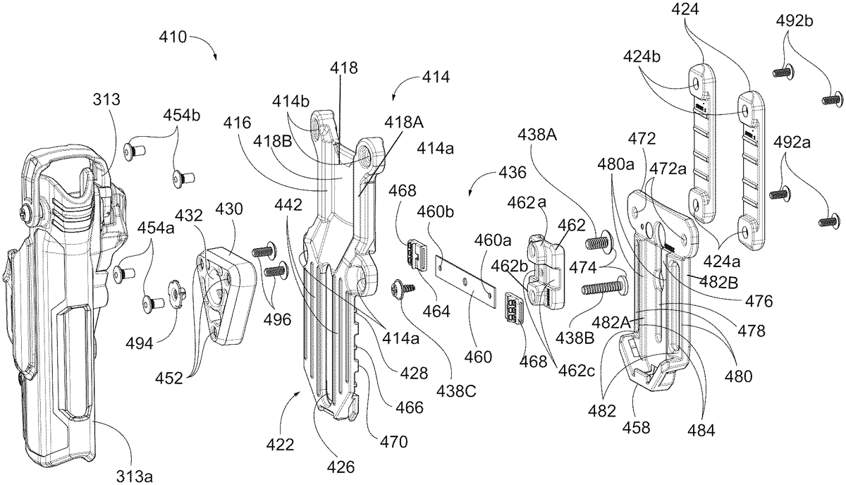
The patent describes a holster support assembly designed to securely attach a holster to a user’s belt, featuring a column portion with adjustable ride height positions and a holster attachment portion. It includes a slider mechanism for smooth movement and a leaf spring for stability, allowing for customizable positioning of the holster.
Claim 1
1 . A holster support assembly configured for supporting a holster on a user’s belt, the holster support assembly comprising: a belt engaging member comprising: a column portion comprising: a front face configured to face the holster; a rear face configured to face the user; and a holster attachment portion; and at least one belt loop portion extending from the rear face of the column portion and configured to engage the user’s belt; wherein the holster attachment portion comprises: a central slot; a plurality of pairs of diametrically opposed slots on the rear face, defining a plurality of ride height positions, wherein the slots of each pair of diametrically opposed slots are on opposite sides of the central slot; a holster carrier comprising: a front face configured to be mounted to the holster; and a rear face configured for sliding movement relative to the front face of the column portion; a slider slideably mounted to the rear face of the holster carrier and comprising: a carrier sled; at least two sliding elements forwardly projecting from the carrier sled and configured for sliding movement within the central slot and preventing torque between the slider and the holster carrier; at least two sliding element fasteners configured for joining the slider to the holster carrier; a leaf spring attached to the carrier sled and having first and second ends configured to be selectively engageable with and disengageable with the pairs of diametrically opposed slots, wherein the leaf spring is configured to be disposed between the rear face of the column portion and the user; and a detent recess disposed near each end of the leaf spring and configured to be engageable with a detent projection disposed in each of the diametrically opposed slots; wherein the holster support assembly further comprises a backing plate attached to the rear face of the belt engaging member and configured for encapsulating the carrier sled. a belt engaging member comprising: a column portion comprising: a front face configured to face the holster; a rear face configured to face the user; and a holster attachment portion; and a column portion comprising: a front face configured to face the holster; a rear face configured to face the user; and a holster attachment portion; and at least one belt loop portion extending from the rear face of the column portion and configured to engage the user’s belt; wherein the holster attachment portion comprises: a central slot; a plurality of pairs of diametrically opposed slots on the rear face, defining a plurality of ride height positions, wherein the slots of each pair of diametrically opposed slots are on opposite sides of the central slot; a central slot; a plurality of pairs of diametrically opposed slots on the rear face, defining a plurality of ride height positions, wherein the slots of each pair of diametrically opposed slots are on opposite sides of the central slot; a holster carrier comprising: a front face configured to be mounted to the holster; and a rear face configured for sliding movement relative to the front face of the column portion; a front face configured to be mounted to the holster; and a rear face configured for sliding movement relative to the front face of the column portion; a slider slideably mounted to the rear face of the holster carrier and comprising: a carrier sled; at least two sliding elements forwardly projecting from the carrier sled and configured for sliding movement within the central slot and preventing torque between the slider and the holster carrier; at least two sliding element fasteners configured for joining the slider to the holster carrier; a leaf spring attached to the carrier sled and having first and second ends configured to be selectively engageable with and disengageable with the pairs of diametrically opposed slots, wherein the leaf spring is configured to be disposed between the rear face of the column portion and the user; and a detent recess disposed near each end of the leaf spring and configured to be engageable with a detent projection disposed in each of the diametrically opposed slots; wherein the holster support assembly further comprises a backing plate attached to the rear face of the belt engaging member and configured for encapsulating the carrier sled. a carrier sled; at least two sliding elements forwardly projecting from the carrier sled and configured for sliding movement within the central slot and preventing torque between the slider and the holster carrier; at least two sliding element fasteners configured for joining the slider to the holster carrier; a leaf spring attached to the carrier sled and having first and second ends configured to be selectively engageable with and disengageable with the pairs of diametrically opposed slots, wherein the leaf spring is configured to be disposed between the rear face of the column portion and the user; and a detent recess disposed near each end of the leaf spring and configured to be engageable with a detent projection disposed in each of the diametrically opposed slots; wherein the holster support assembly further comprises a backing plate attached to the rear face of the belt engaging member and configured for encapsulating the carrier sled.
Google Patents
https://patents.google.com/patent/US12716686
USPTO PDF
https://image-ppubs.uspto.gov/dirsearch-public/print/downloadPdf/12716686