US12704340 - Firearm sound suppressor with peripheral venting
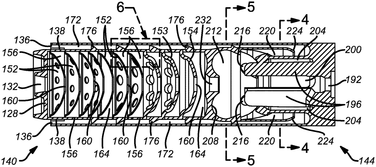
This patent describes a firearm suppressor designed to reduce muzzle blast and flash by utilizing a series of cylindrical gas expansion chambers and an annular gas expansion chamber that directs propellant gases to peripheral vents. The suppressor features a rear portion with a curved interior surface that deflects gases, enhancing the suppression effect while withstanding high pressure and temperature.
Claim 1
1 . A suppressor for a firearm, comprising: a housing having a proximal end and a distal end; a front portion for attenuating temperature and energy of propellant gases and comprising a series of baffles; an annular gas expansion chamber disposed between an outside surface of a plurality of spacers and an inner surface of the housing, the annular gas expansion chamber comprising a continuous chamber surrounding a series of cylindrical gas expansion chambers and extending along a portion of the suppressor’s length, and configured for directing a portion of the propellant gases distally to peripheral vents disposed at the distal end; a plurality of circumferential apertures disposed radially between each of the cylindrical gas expansion chambers and the annular gas expansion chamber; and a rear portion comprising a back end member defining a lateral gas expansion chamber and a primary gas expansion chamber for deflecting and rebounding a portion of the propellant gases before entering the annular gas expansion chamber; wherein the back end member comprises at least one curved interior surface adapted to deflect a portion of the propellant gases toward one or more vents disposed at a rear of the primary gas expansion chamber; wherein the at least one curved interior surface is configured to withstand pressure and temperature of the propellant gases; wherein the suppressor is configured to divert a first portion of the propellant gases deflected by the at least one curved interior surface through the annular gas expansion chamber prior to mixing the first portion of the propellant gases with a second portion of the propellant gases introduced through the plurality of circumferential apertures into the annular gas expansion chamber; wherein the primary gas expansion chamber and the one or more vents include one or more ledges for directing the propellant gases toward a blast suppression chamber; and wherein the blast suppression chamber is disposed between a tapered blast deflector and a portion of the at least one curved interior surface, such that the blast suppression chamber surrounds the lateral gas expansion chamber. a housing having a proximal end and a distal end; a front portion for attenuating temperature and energy of propellant gases and comprising a series of baffles; an annular gas expansion chamber disposed between an outside surface of a plurality of spacers and an inner surface of the housing, the annular gas expansion chamber comprising a continuous chamber surrounding a series of cylindrical gas expansion chambers and extending along a portion of the suppressor’s length, and configured for directing a portion of the propellant gases distally to peripheral vents disposed at the distal end; a plurality of circumferential apertures disposed radially between each of the cylindrical gas expansion chambers and the annular gas expansion chamber; and a rear portion comprising a back end member defining a lateral gas expansion chamber and a primary gas expansion chamber for deflecting and rebounding a portion of the propellant gases before entering the annular gas expansion chamber; wherein the back end member comprises at least one curved interior surface adapted to deflect a portion of the propellant gases toward one or more vents disposed at a rear of the primary gas expansion chamber; wherein the at least one curved interior surface is configured to withstand pressure and temperature of the propellant gases; wherein the suppressor is configured to divert a first portion of the propellant gases deflected by the at least one curved interior surface through the annular gas expansion chamber prior to mixing the first portion of the propellant gases with a second portion of the propellant gases introduced through the plurality of circumferential apertures into the annular gas expansion chamber; wherein the primary gas expansion chamber and the one or more vents include one or more ledges for directing the propellant gases toward a blast suppression chamber; and wherein the blast suppression chamber is disposed between a tapered blast deflector and a portion of the at least one curved interior surface, such that the blast suppression chamber surrounds the lateral gas expansion chamber.
Google Patents
https://patents.google.com/patent/US12704340
USPTO PDF
https://image-ppubs.uspto.gov/dirsearch-public/print/downloadPdf/12704340