US12674641 - Propulsion module assembly for a projectile launcher
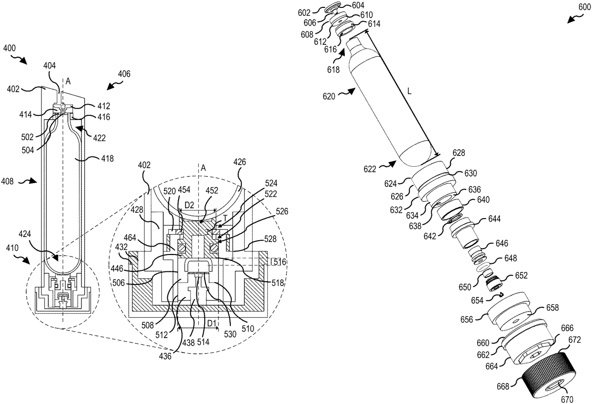
The patent describes a propulsion module assembly for a projectile launcher that includes a puncher system designed to translate a puncher head within a casing to fluidly connect a propulsion source to a fluid channel. This system features mechanisms for securing the puncher head and controlling its movement, enhancing the activation process of the projectile launcher.
Claim 1
1 . A puncher system associated with a propulsion system for a projectile launcher, the puncher system comprising: a puncher casing having a first end opposite a second end and a puncher channel extending at least partially between the first end and the second end; a puncher drive being proximate to the first end of the puncher casing and in communication with the puncher channel; a puncher head being proximate to the first end of the puncher casing within the puncher channel, wherein the puncher head is configured to translate from the first end to the second end responsive to a drive force and via the puncher channel; a puncher lock being proximate to the second end of the puncher casing within the puncher casing, wherein the puncher lock is configured to secure the puncher head proximate to the second end; and a puncher casing cap of the puncher casing is configured to define a lock recess and a lock stop, the lock recess configured to contain the puncher lock in a first position at a first time and the lock stop configured to secure the puncher lock and the puncher head in a second position at a second time. a puncher casing having a first end opposite a second end and a puncher channel extending at least partially between the first end and the second end; a puncher drive being proximate to the first end of the puncher casing and in communication with the puncher channel; a puncher head being proximate to the first end of the puncher casing within the puncher channel, wherein the puncher head is configured to translate from the first end to the second end responsive to a drive force and via the puncher channel; a puncher lock being proximate to the second end of the puncher casing within the puncher casing, wherein the puncher lock is configured to secure the puncher head proximate to the second end; and a puncher casing cap of the puncher casing is configured to define a lock recess and a lock stop, the lock recess configured to contain the puncher lock in a first position at a first time and the lock stop configured to secure the puncher lock and the puncher head in a second position at a second time.
Google Patents
https://patents.google.com/patent/US12674641
USPTO PDF
https://image-ppubs.uspto.gov/dirsearch-public/print/downloadPdf/12674641