US12601577 - Quick disconnect coupler for rocket motor
The patent describes a quick disconnect coupler system designed for aeronautical platforms, featuring a cylindrical housing, a rotating spin member, and a plunger mechanism that facilitates the coupling and uncoupling of sections. The system utilizes springs and a ball coupler mechanism to ensure secure attachment and easy disengagement in response to platform acceleration.
Claim 1
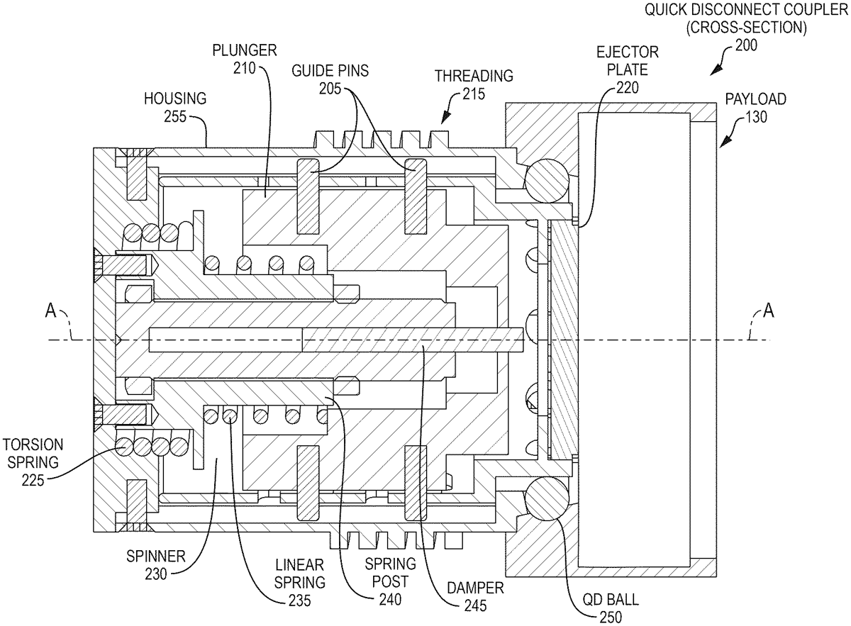
1 . A coupler system for coupling first and second sections of an aeronautical platform, the coupler system comprising: a cylindrical housing configured to be fixedly attached to the first section; a spin member disposed within the housing and configured to rotate about a longitudinal axis of the platform; a groove pattern etched into the spin member; a plunger disposed within the spin member and configured to move linearly along the longitudinal axis; a first spring configured to cause the linear movement of the plunger in response to acceleration of the platform; a guide pin attached to the plunger, the guide pin extending radially outward toward the housing and configured to travel along the groove pattern as the plunger moves; a ball coupler mechanism configured to provide mechanical attachment of the coupler system to the second section; and a second spring configured to rotate the spin member, such that a combination of the movement of the plunger and the rotation of the spinner cause the ball coupler mechanism to disengage from the second section. a cylindrical housing configured to be fixedly attached to the first section; a spin member disposed within the housing and configured to rotate about a longitudinal axis of the platform; a groove pattern etched into the spin member; a plunger disposed within the spin member and configured to move linearly along the longitudinal axis; a first spring configured to cause the linear movement of the plunger in response to acceleration of the platform; a guide pin attached to the plunger, the guide pin extending radially outward toward the housing and configured to travel along the groove pattern as the plunger moves; a ball coupler mechanism configured to provide mechanical attachment of the coupler system to the second section; and a second spring configured to rotate the spin member, such that a combination of the movement of the plunger and the rotation of the spinner cause the ball coupler mechanism to disengage from the second section.
Google Patents
https://patents.google.com/patent/US12601577
USPTO PDF
https://image-ppubs.uspto.gov/dirsearch-public/print/downloadPdf/12601577