US12782075 - Firearm suppression device
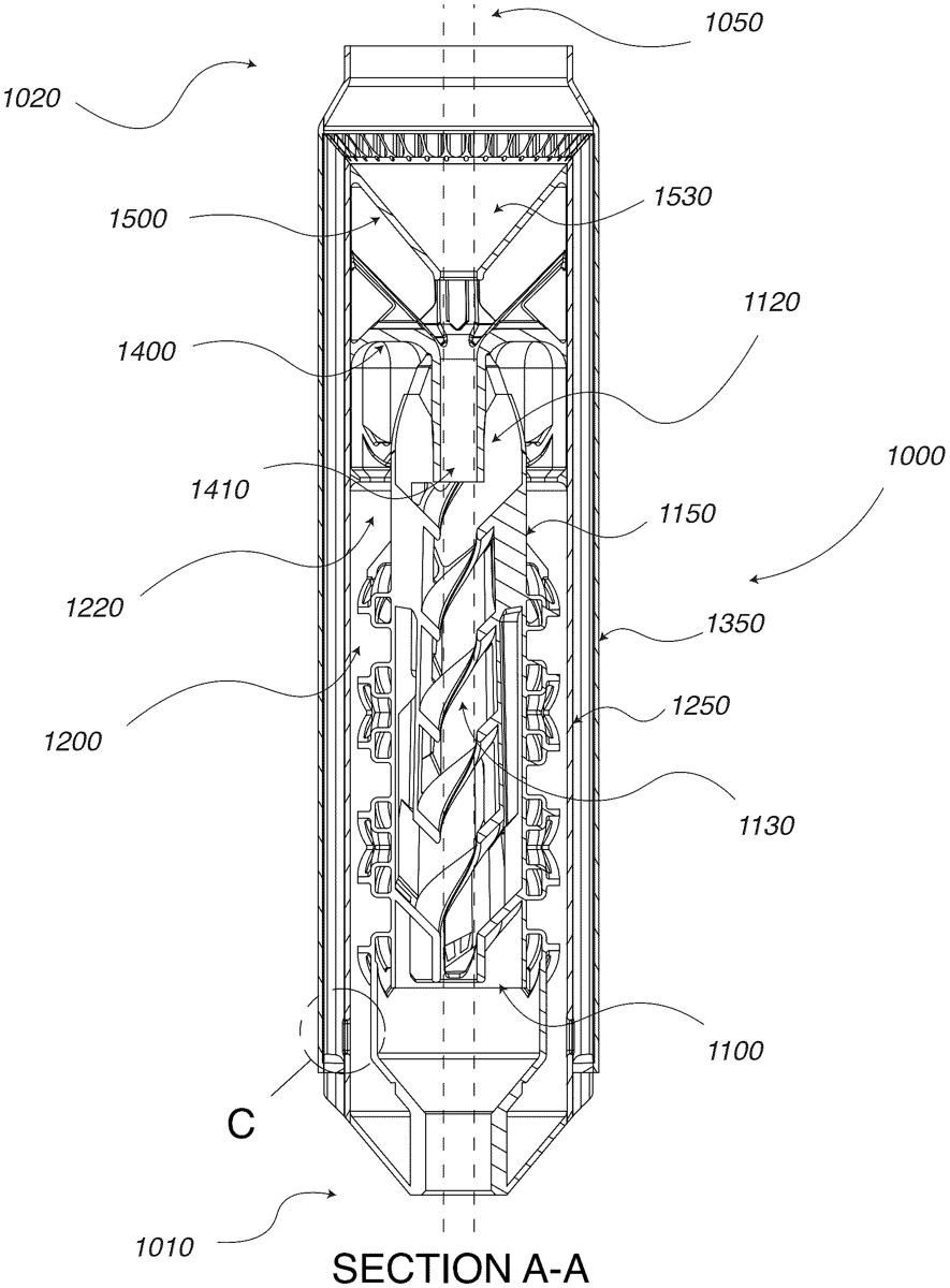
The patent describes a multi-stage firearm suppression device designed to control and direct expanding muzzle-blast gases, enhancing cooling and reducing the weapon’s firing signature. It features concentric volumes, helical tubes, and cooling mechanisms that work together to vent gases away from the operator while improving overall performance.
Claim 1
1 . A suppression device for firearms comprising: a proximal aspect configured to be interconnected with a muzzle-end of a firearm, a distal aspect configured to vent to environment, and a pathway axially therethrough adapted to allow passage of a projectile therethrough; a first volume concentrically surrounds the pathway and extends from the proximal aspect of the suppression device towards the distal aspect of the suppression device, wherein the first volume comprises helical elements adapted to direct gases radially outward from the pathway and toward the distal aspect of the suppression device; a first baffle located distally from the first volume, wherein the first baffle is configured to direct gases from a distal aspect of the first volume, radially outward and into a distal aspect of a second volume; the second volume concentrically surrounds the first volume, wherein gases within the second volume flow toward the proximal aspect of the suppression device via a plurality of apertures located at a proximal aspect of the second volume, wherein each aperture is fluidly interconnected to a vent tube, wherein each of the vent tubes comprises distally located open end, and wherein the vent tubes are configured to direct gas toward the distal aspect of the suppression device for venting; a plurality of helical tubes, including a first helical tube having a form which rotates in a first direction, and a second helical tube having a form which rotates in a second direction, counter to the first direction, interconnected to an external boundary of the first volume, wherein the plurality of helical tubes receive a first portion of the gases at a proximal aspect of the plurality of helical tubes and direct the first portion of the gases in a distal direction, wherein a distal aspect of the plurality of helical tubes direct gases into the distal aspect of the second volume; the first volume receives a second portion of the gases, wherein the first portion of the gases and the second portion of the gases intermix within the second volume; the plurality of helical tubes are in fluid communication with each other at intersection locations, and sidewalls of the plurality of helical tubes extend into the second volume; a proximal aspect configured to be interconnected with a muzzle-end of a firearm, a distal aspect configured to vent to environment, and a pathway axially therethrough adapted to allow passage of a projectile therethrough; a first volume concentrically surrounds the pathway and extends from the proximal aspect of the suppression device towards the distal aspect of the suppression device, wherein the first volume comprises helical elements adapted to direct gases radially outward from the pathway and toward the distal aspect of the suppression device; a first baffle located distally from the first volume, wherein the first baffle is configured to direct gases from a distal aspect of the first volume, radially outward and into a distal aspect of a second volume; the second volume concentrically surrounds the first volume, wherein gases within the second volume flow toward the proximal aspect of the suppression device via a plurality of apertures located at a proximal aspect of the second volume, wherein each aperture is fluidly interconnected to a vent tube, wherein each of the vent tubes comprises distally located open end, and wherein the vent tubes are configured to direct gas toward the distal aspect of the suppression device for venting; a plurality of helical tubes, including a first helical tube having a form which rotates in a first direction, and a second helical tube having a form which rotates in a second direction, counter to the first direction, interconnected to an external boundary of the first volume, wherein the plurality of helical tubes receive a first portion of the gases at a proximal aspect of the plurality of helical tubes and direct the first portion of the gases in a distal direction, wherein a distal aspect of the plurality of helical tubes direct gases into the distal aspect of the second volume; the first volume receives a second portion of the gases, wherein the first portion of the gases and the second portion of the gases intermix within the second volume; the plurality of helical tubes are in fluid communication with each other at intersection locations, and sidewalls of the plurality of helical tubes extend into the second volume; a plurality of turbulence inducing elements interconnected to the plurality of helical tubes which are configured to induce turbulence within the second volume; an expansion feature located distally from the volumes, the expansion feature comprises a form of increasing volume directed toward the distal aspect of the suppression device, wherein the pathway extends therethrough, and wherein the expansion feature is configured to create a low-pressure zone when the projectile passes therethrough, a plurality of cooling tubes interconnected with an external boundary of the second volume, each cooling tube comprising a first end open to the environment at a proximal aspect of the suppression device, and each cooling tube further comprising an open second end at the distal aspect of the suppression device, wherein the second end of the cooling tubes and the open end of the vent tubes are coincident with the low-pressure zone, wherein the low-pressure zone is configured to draw gases through the vent tubes, and further draw ambient air through the cooling tubes; and a compression feature distally located from the expansion feature, wherein the compression feature constricts in volume as it approaches the distal aspect of the suppression device, resulting in a high-pressure zone distally located from the low-pressure zone, and prior to venting to the environment. an expansion feature located distally from the volumes, the expansion feature comprises a form of increasing volume directed toward the distal aspect of the suppression device, wherein the pathway extends therethrough, and wherein the expansion feature is configured to create a low-pressure zone when the projectile passes therethrough, a plurality of cooling tubes interconnected with an external boundary of the second volume, each cooling tube comprising a first end open to the environment at a proximal aspect of the suppression device, and each cooling tube further comprising an open second end at the distal aspect of the suppression device, wherein the second end of the cooling tubes and the open end of the vent tubes are coincident with the low-pressure zone, wherein the low-pressure zone is configured to draw gases through the vent tubes, and further draw ambient air through the cooling tubes; and a compression feature distally located from the expansion feature, wherein the compression feature constricts in volume as it approaches the distal aspect of the suppression device, resulting in a high-pressure zone distally located from the low-pressure zone, and prior to venting to the environment.
Google Patents
https://patents.google.com/patent/US12782075
USPTO PDF
https://image-ppubs.uspto.gov/dirsearch-public/print/downloadPdf/12782075