US12768627 - Connection system
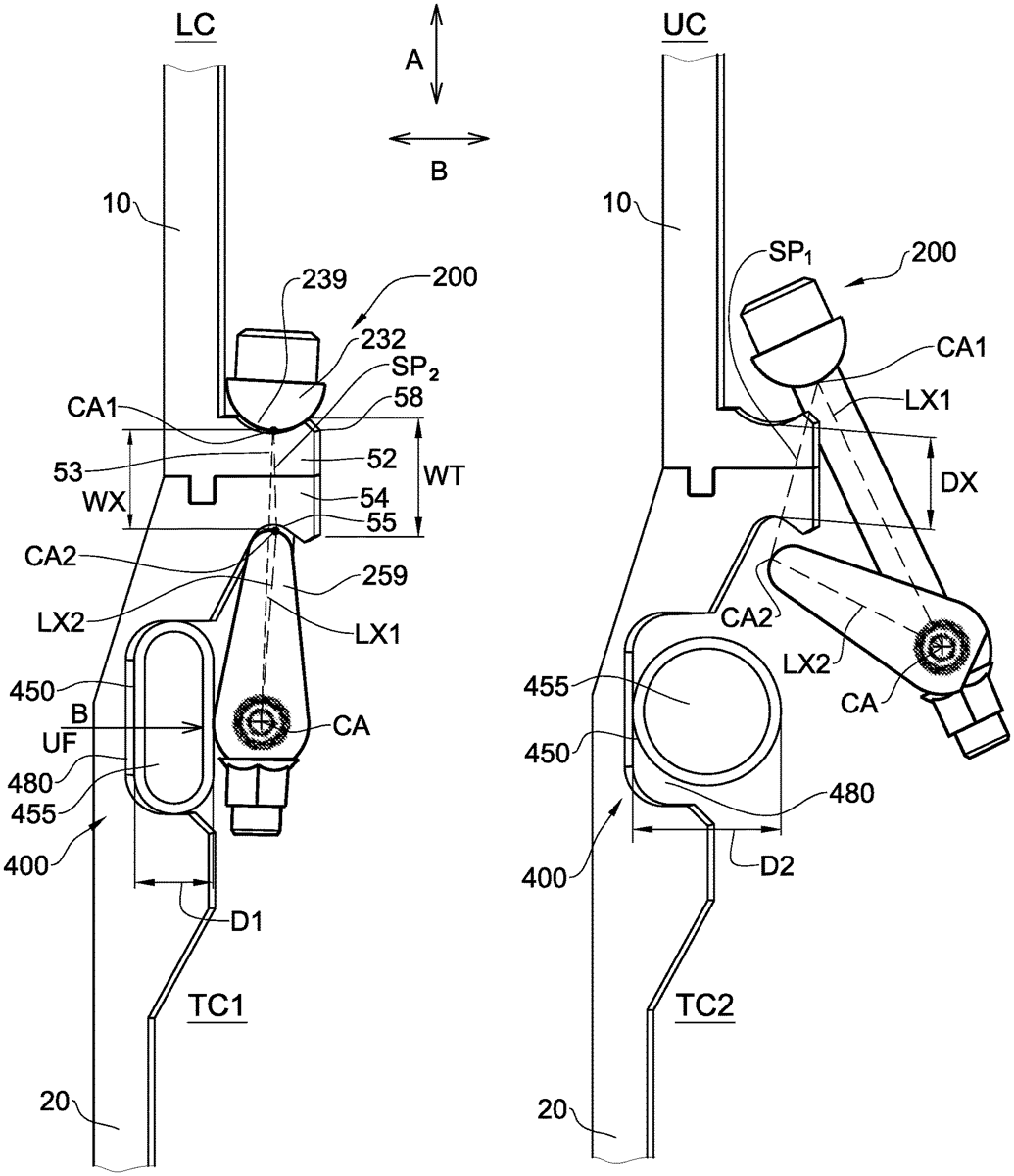
The patent describes a connection system designed to releasably connect two components using a locking device that can transition between locked and unlocked configurations through an actuator. This system employs pivotably mounted linkage elements that enable a clamped relationship and allows for the selective application of unlocking forces to facilitate the release of the components.
Claim 1
1 . A connection system for releasably connecting a first component and a second component in a first direction, the connection system comprising: at least one locking device having a geometrically locked configuration and an unlocked configuration, wherein in the geometrically locked configuration the locking device is capable of reversibly geometrically locking together the first component and the second component in a mutually clamped relationship along said first direction, each said locking device comprising at least two linkage elements pivotably mounted to one another about a common clamp axis to thereby enable each said linkage element to pivot about the common clamp axis, and wherein in said geometrically locked configuration said at least two linkage elements are in an over-center position; and an actuator device configured for transitioning said at least one locking device from the geometrically locked configuration to the unlocked configuration by selectively applying to each said locking device an unlocking force directly to said linkage elements at the common clamp axis, in a second direction, whereby to cause the at least two linkage elements to pivot with respect to one another about the common clamp axis and thereby cause the at least two linkage elements to be released from the over-center position and into an under-center position, and wherein said first direction and said second direction are non-parallel with respect to one another; wherein said actuator device comprises a tube element configured for shape morphing from a first tube configuration having a first tube dimension parallel to said second direction, and a second tube configuration having a second tube dimension parallel to said second direction, wherein said second tube dimension is significantly greater than said first tube dimension. at least one locking device having a geometrically locked configuration and an unlocked configuration, wherein in the geometrically locked configuration the locking device is capable of reversibly geometrically locking together the first component and the second component in a mutually clamped relationship along said first direction, each said locking device comprising at least two linkage elements pivotably mounted to one another about a common clamp axis to thereby enable each said linkage element to pivot about the common clamp axis, and wherein in said geometrically locked configuration said at least two linkage elements are in an over-center position; and an actuator device configured for transitioning said at least one locking device from the geometrically locked configuration to the unlocked configuration by selectively applying to each said locking device an unlocking force directly to said linkage elements at the common clamp axis, in a second direction, whereby to cause the at least two linkage elements to pivot with respect to one another about the common clamp axis and thereby cause the at least two linkage elements to be released from the over-center position and into an under-center position, and wherein said first direction and said second direction are non-parallel with respect to one another; wherein said actuator device comprises a tube element configured for shape morphing from a first tube configuration having a first tube dimension parallel to said second direction, and a second tube configuration having a second tube dimension parallel to said second direction, wherein said second tube dimension is significantly greater than said first tube dimension.
Google Patents
https://patents.google.com/patent/US12768627
USPTO PDF
https://image-ppubs.uspto.gov/dirsearch-public/print/downloadPdf/12768627