US12753984 - Firearm and extractor, bolt and trigger pin assembly
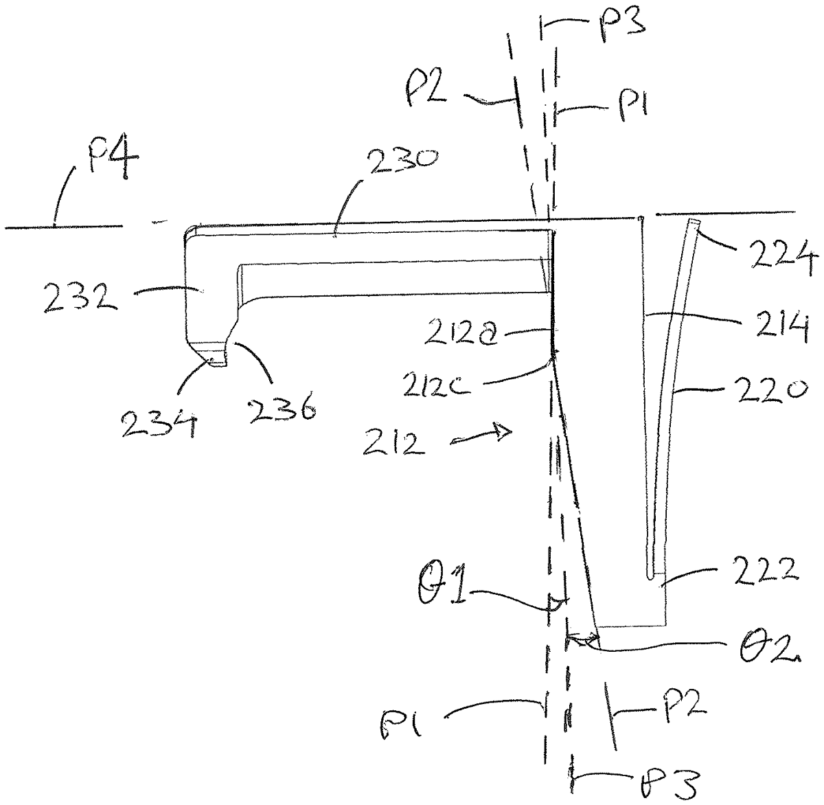
The patent describes a cartridge extractor designed to engage and disengage a cartridge case during a firearm’s firing cycle, featuring a unitary annular body that pivots relative to the bolt head. Additionally, it includes a pin assembly for securing a trigger and an adjustable bolt handle capable of transferring high loads.
Claim 1
1 . A cartridge extractor for temporarily engaging a cartridge case during a firing cycle of a firearm, the cartridge extractor including: a unitary annular extractor body for positioning about a portion of a firearm bolt, the annular extractor body including an outer curved surface that defines an outer perimeter of the annular extractor body, an inner curved surface that defines an inner perimeter of the annular extractor body, a first axial face extending between the outer curved surface and the inner curved surface, a second axial face extending between the outer curved surface and the inner curved surface and spaced apart from the first axial face in an axial direction, an arm extending axially from the first axial face, the arm having a cartridge engager flange distal from the annular extractor body, wherein the annular extractor body is pivotably mounted relative to a head of the firearm bolt and is configured to pivot between a cartridge engagement position and a cartridge disengagement position. a unitary annular extractor body for positioning about a portion of a firearm bolt, the annular extractor body including an outer curved surface that defines an outer perimeter of the annular extractor body, an inner curved surface that defines an inner perimeter of the annular extractor body, a first axial face extending between the outer curved surface and the inner curved surface, a second axial face extending between the outer curved surface and the inner curved surface and spaced apart from the first axial face in an axial direction, an arm extending axially from the first axial face, the arm having a cartridge engager flange distal from the annular extractor body, wherein an outer curved surface that defines an outer perimeter of the annular extractor body, an inner curved surface that defines an inner perimeter of the annular extractor body, a first axial face extending between the outer curved surface and the inner curved surface, a second axial face extending between the outer curved surface and the inner curved surface and spaced apart from the first axial face in an axial direction, an arm extending axially from the first axial face, the arm having a cartridge engager flange distal from the annular extractor body, wherein the annular extractor body is pivotably mounted relative to a head of the firearm bolt and is configured to pivot between a cartridge engagement position and a cartridge disengagement position.
Google Patents
https://patents.google.com/patent/US12753984
USPTO PDF
https://image-ppubs.uspto.gov/dirsearch-public/print/downloadPdf/12753984