US12747932 - Firearm optical sight, system and method
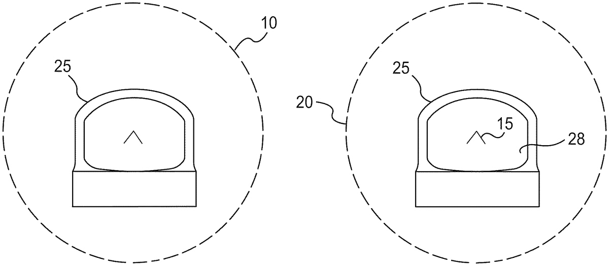
The patent describes an optical sight for firearms that utilizes a partially reflective optical element and an array of light-emitting diodes to project a reticle pattern, indicating alignment with a target. It features multi-mode operation to alternate between a complete reticle with aiming and non-aiming marks and a partial reticle displaying only the aiming marks.
Claim 1
1 . An optical sight for a firearm, comprising: a partially reflective optical element; electronic components including: electric circuitry; a power source; and an array of resonant cavity light-emitting diodes for emitting light towards the partially reflective optical element; a reflective image projected onto the partially reflective optical element by the array of resonant cavity light-emitting diodes, the reflective image including a reticle pattern according to a configuration of the array of resonant cavity light-emitting diodes, the reticle pattern comprising one or more aiming marks and one or more non-aiming marks; wherein at an operable field of view for the optical sight, when the optical sight is aligned with an intended target for the optical sight, then the one or more aiming marks are in the operable field of view and the one or more non-aiming marks are outside the operable field of view; and wherein the electric circuitry is operationally configured for multi-mode operation of the optical sight for alternating the projected reflective image of the reticle between a complete reticle including the one or more aiming marks and the one or more non-aiming marks and a partial reticle including only the one or more aiming marks. a partially reflective optical element; electronic components including: electric circuitry; a power source; and an array of resonant cavity light-emitting diodes for emitting light towards the partially reflective optical element; electric circuitry; a power source; and an array of resonant cavity light-emitting diodes for emitting light towards the partially reflective optical element; a reflective image projected onto the partially reflective optical element by the array of resonant cavity light-emitting diodes, the reflective image including a reticle pattern according to a configuration of the array of resonant cavity light-emitting diodes, the reticle pattern comprising one or more aiming marks and one or more non-aiming marks; wherein at an operable field of view for the optical sight, when the optical sight is aligned with an intended target for the optical sight, then the one or more aiming marks are in the operable field of view and the one or more non-aiming marks are outside the operable field of view; and wherein the electric circuitry is operationally configured for multi-mode operation of the optical sight for alternating the projected reflective image of the reticle between a complete reticle including the one or more aiming marks and the one or more non-aiming marks and a partial reticle including only the one or more aiming marks.
Google Patents
https://patents.google.com/patent/US12747932
USPTO PDF
https://image-ppubs.uspto.gov/dirsearch-public/print/downloadPdf/12747932