US12729925 - Bow string cam arrangement for a bow
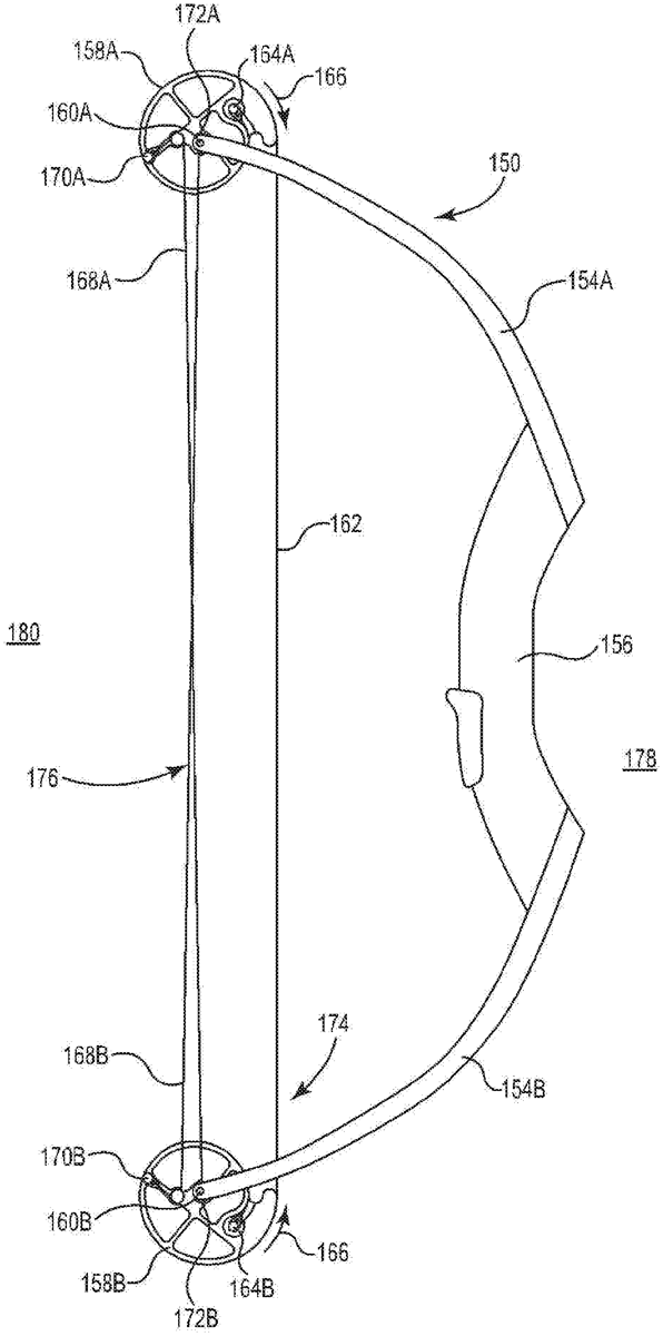
The patent describes a dual-cam archery bow featuring a unique arrangement of power cable journals that allow for simultaneous take-up and let-out during the drawing process. This design enhances the bow’s performance by optimizing the draw force relative to the draw distance through the strategic placement of the draw string and power cables.
Claim 1
1 . A bow comprising: a riser including an up-range side positioned proximate a user and a down-range side positioned proximate a target; at least one first bow limb attached to the riser and extending at least partially in an up-range direction relative to the up-range side of the riser; at least one second bow limb attached to the riser and extending at least partially in the up-range direction relative to the up-range side of the riser; a first cam mounted to the at least one first bow limb and rotatable around a first axis within a first plane of rotation perpendicular to the first axis, the first cam comprising a first draw string journal, a first power cable journal extending in a direction perpendicular to the first plane of rotation, and a second power cable journal extending in a direction perpendicular to the first plane of rotation, wherein the first power cable journal and the second power cable journal each define a path configured to engage a cable, the path at least partially extending at an angle relative to the first plane of rotation; a second cam mounted to the at least one second bow limb and rotatable around a second axis within a second plane of rotation perpendicular to the second axis, the second cam comprising a second draw string journal, a third power cable journal extending in a direction perpendicular to the second plane of rotation, and a fourth power cable journal extending in a direction perpendicular to the second plane of rotation, wherein the third power cable journal and the fourth power cable journal each define a path configured to engage a cable, the path extending at least partially at an angle relative to the second plane of rotation; a draw string configured to launch a projectile along a projectile axis, the draw string received in the first and second draw string journals and secured to the first and second cams, wherein the draw string unwinds from the first and second draw string journals as the draw string translates from a released configuration to a drawn configuration, wherein: in the released configuration, a first portion of the draw string is received in the first draw string journal, a second portion of the draw string is received in the second draw string journal, and a third portion of the draw string extends linearly: (1) between the first cam and the second cam, (2) directly from a down-range side of the first cam, the down-range side of the first cam positioned down-range relative to the first axis and located between the riser and the first axis, and (3) directly from a down-range side of the second cam, the down-range side of the second cam positioned down-range relative to the second axis and located between the riser and the second axis; and in the drawn configuration, the first portion of the draw string, the second portion of the draw string, and the third portion of the draw string are positioned to the up-range side of the riser; and a first power cable and a second power cable, the first power cable attached to the first cam and the second cam, the second power cable attached to the first cam and the second cam, wherein a first portion of the first power cable is received in the first power cable journal and a second portion of the first power cable is received in the fourth power cable journal, and wherein a first portion of the second power cable is received in the second power cable journal and a second portion of the second power cable is received in the third power cable journal, wherein, during operation of the bow as the draw string moves from the released configuration to the drawn configuration, the first portion of the first power cable and the first portion of the second power cable are displaced along the first axis relative to the first plane of rotation of the first draw string journal and the second portion of the first power cable and the second portion of the second power cable are displaced along the second axis relative to the second plane of rotation of the second draw string journal, and wherein a draw force versus draw distance of the bow is determined at least in part by relative rates of take-up and let-out of the first power cable journal and the second power cable journal. a riser including an up-range side positioned proximate a user and a down-range side positioned proximate a target; at least one first bow limb attached to the riser and extending at least partially in an up-range direction relative to the up-range side of the riser; at least one second bow limb attached to the riser and extending at least partially in the up-range direction relative to the up-range side of the riser; a first cam mounted to the at least one first bow limb and rotatable around a first axis within a first plane of rotation perpendicular to the first axis, the first cam comprising a first draw string journal, a first power cable journal extending in a direction perpendicular to the first plane of rotation, and a second power cable journal extending in a direction perpendicular to the first plane of rotation, wherein the first power cable journal and the second power cable journal each define a path configured to engage a cable, the path at least partially extending at an angle relative to the first plane of rotation; a second cam mounted to the at least one second bow limb and rotatable around a second axis within a second plane of rotation perpendicular to the second axis, the second cam comprising a second draw string journal, a third power cable journal extending in a direction perpendicular to the second plane of rotation, and a fourth power cable journal extending in a direction perpendicular to the second plane of rotation, wherein the third power cable journal and the fourth power cable journal each define a path configured to engage a cable, the path extending at least partially at an angle relative to the second plane of rotation; a draw string configured to launch a projectile along a projectile axis, the draw string received in the first and second draw string journals and secured to the first and second cams, wherein the draw string unwinds from the first and second draw string journals as the draw string translates from a released configuration to a drawn configuration, wherein: in the released configuration, a first portion of the draw string is received in the first draw string journal, a second portion of the draw string is received in the second draw string journal, and a third portion of the draw string extends linearly: (1) between the first cam and the second cam, (2) directly from a down-range side of the first cam, the down-range side of the first cam positioned down-range relative to the first axis and located between the riser and the first axis, and (3) directly from a down-range side of the second cam, the down-range side of the second cam positioned down-range relative to the second axis and located between the riser and the second axis; and in the drawn configuration, the first portion of the draw string, the second portion of the draw string, and the third portion of the draw string are positioned to the up-range side of the riser; and in the released configuration, a first portion of the draw string is received in the first draw string journal, a second portion of the draw string is received in the second draw string journal, and a third portion of the draw string extends linearly: (1) between the first cam and the second cam, (2) directly from a down-range side of the first cam, the down-range side of the first cam positioned down-range relative to the first axis and located between the riser and the first axis, and (3) directly from a down-range side of the second cam, the down-range side of the second cam positioned down-range relative to the second axis and located between the riser and the second axis; and in the drawn configuration, the first portion of the draw string, the second portion of the draw string, and the third portion of the draw string are positioned to the up-range side of the riser; and a first power cable and a second power cable, the first power cable attached to the first cam and the second cam, the second power cable attached to the first cam and the second cam, wherein a first portion of the first power cable is received in the first power cable journal and a second portion of the first power cable is received in the fourth power cable journal, and wherein a first portion of the second power cable is received in the second power cable journal and a second portion of the second power cable is received in the third power cable journal, wherein, during operation of the bow as the draw string moves from the released configuration to the drawn configuration, the first portion of the first power cable and the first portion of the second power cable are displaced along the first axis relative to the first plane of rotation of the first draw string journal and the second portion of the first power cable and the second portion of the second power cable are displaced along the second axis relative to the second plane of rotation of the second draw string journal, and wherein a draw force versus draw distance of the bow is determined at least in part by relative rates of take-up and let-out of the first power cable journal and the second power cable journal.
Google Patents
https://patents.google.com/patent/US12729925
USPTO PDF
https://image-ppubs.uspto.gov/dirsearch-public/print/downloadPdf/12729925