US12723841 - Volumetric LED alignment aid for sighting device
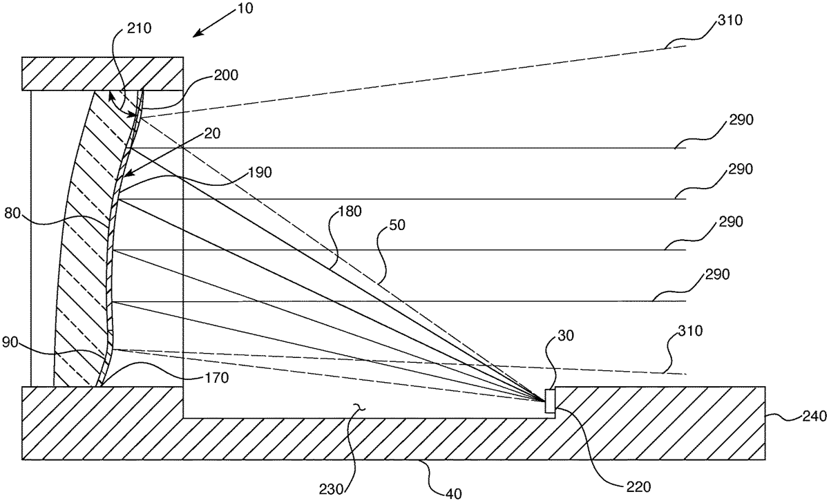
The patent describes a sighting device designed to enhance a shooter’s aiming accuracy by incorporating a disk optical element with reflective coatings and a light source that provides alignment feedback. This innovative apparatus aims to improve target acquisition through visual cues, leveraging specific light wavelengths to assist in aiming.
Claim 1
1 . A sighting device to assist a shooter in aiming at a target, the sighting device comprising: a frame housing coupled to a disk optical element, wherein the disk optical element comprises: a concave surface comprising an inner surface, an outer surface, and an outer edge, the outer edge comprising a curvature that is less than that of a curvature of the concave surface; a first coating disposed on the inner concave surface, wherein the first coating comprises a reflective material; a second coating disposed on the outer edge of the concave surface, wherein the second coating comprises reflective material and the second coating is patterned; and a light source coupled to a mount located at a focal point of the disk optical element wherein emission of light from the light source faces the disk optical element. a frame housing coupled to a disk optical element, wherein the disk optical element comprises: a concave surface comprising an inner surface, an outer surface, and an outer edge, the outer edge comprising a curvature that is less than that of a curvature of the concave surface; a first coating disposed on the inner concave surface, wherein the first coating comprises a reflective material; a second coating disposed on the outer edge of the concave surface, wherein the second coating comprises reflective material and the second coating is patterned; and a light source coupled to a mount located at a focal point of the disk optical element wherein emission of light from the light source faces the disk optical element. a concave surface comprising an inner surface, an outer surface, and an outer edge, the outer edge comprising a curvature that is less than that of a curvature of the concave surface; a first coating disposed on the inner concave surface, wherein the first coating comprises a reflective material; a second coating disposed on the outer edge of the concave surface, wherein the second coating comprises reflective material and the second coating is patterned; and a light source coupled to a mount located at a focal point of the disk optical element wherein emission of light from the light source faces the disk optical element.
Google Patents
https://patents.google.com/patent/US12723841
USPTO PDF
https://image-ppubs.uspto.gov/dirsearch-public/print/downloadPdf/12723841