US12716699 - Target stand
The patent describes a target stand designed for impact testing, featuring a frame with two diagonal rails and a trolley that moves between their ends. The trolley is equipped with wheel assemblies that allow it to carry a target object while maintaining its orientation parallel to the ground during movement.
Claim 1
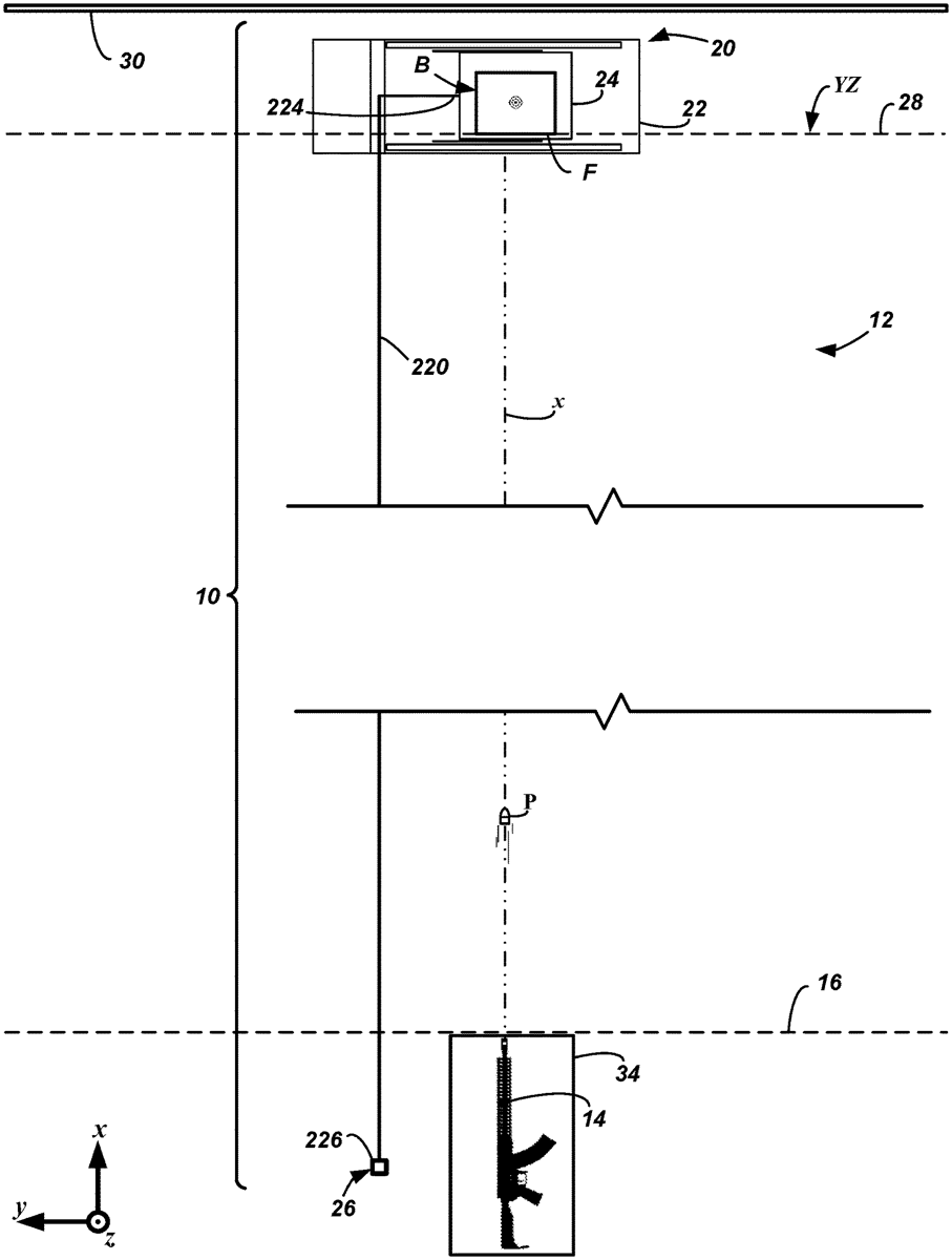
1 . A target stand for carrying a target object under test for impact testing by a projectile from a projectile source, the target stand configured to be arranged relative to level ground and down range of the projectile source, the projectile source configured to fire the projectile along an x-axis, wherein the x-axis is parallel to the level ground and orthogonal to the target stand, a y-axis is parallel to the level ground and orthogonal to the x-axis, and a z-axis is orthogonal to the level ground, the x-axis, and the y-axis, and the target stand comprising: a frame; a first rail supported by the frame and having an upper end and a lower end, the first rail extending diagonally relative to the y-axis and the z-axis from the lower end of the first rail to the upper end of the first rail; a second rail supported by the frame and having an upper end and a lower end, the second rail extending diagonally relative to the y-axis and the z-axis from the lower end of the second rail to the upper end of the second rail; and a trolley disposed between the first rail and the second rail, the trolley including a base, the base being a plate arranged parallel to the y-axis and orthogonal to the z-axis, the base having an upper surface orthogonal to the z-axis, a proximal portion, a cantilevered portion, and a free end, wherein the cantilevered portion of the base extends longitudinally in a direction of the y-axis away from the proximal portion of the base and toward the free end of the base, a first wheel assembly coupled to the proximal portion of the base and in contact with the first rail, and a second wheel assembly coupled to the proximal portion of the base and in contact with the second rail, wherein the first rail is spaced from the second rail relative to the x-axis, and wherein the trolley is movable between the respective lower ends of the first and second rails and the respective upper ends of the first and second rails via the first wheel assembly contacting the first rail and the second wheel assembly contacting the second rail such that in response to the trolley translating from a first position to a second position relative to the first and second rails, the trolley moves diagonally in a first direction relative to the y-axis and the z-axis, and wherein the upper surface of the base of the trolley at the cantilevered portion near the free end of the base is configured to carry the target object, and wherein in response to the trolley moving diagonally in the first direction, the base of the trolley remains parallel to both the y-axis and the level ground and the upper surface of the base remains orthogonal to the z-axis, and wherein the frame comprises a first inclined member and a second inclined member wherein the first rail is coupled to the first inclined member, the second rail is coupled to the second inclined member, and each of the first and second inclined members comprise a series of linearly spaced holes extending along at least a partial length thereof, and wherein the first wheel assembly comprises a wheel portion that comprises a carrier that supports a set of wheels and a stopper portion, and wherein the stopper portion comprises a flange portion that extends from a side of the carrier and a clip that is coupled to the flange portion, wherein the clip comprises a lock that is configured to move within one of the series of linearly spaced holes and retain a position of the trolley relative to the first and second rails. a frame; a first rail supported by the frame and having an upper end and a lower end, the first rail extending diagonally relative to the y-axis and the z-axis from the lower end of the first rail to the upper end of the first rail; a second rail supported by the frame and having an upper end and a lower end, the second rail extending diagonally relative to the y-axis and the z-axis from the lower end of the second rail to the upper end of the second rail; and a trolley disposed between the first rail and the second rail, the trolley including a base, the base being a plate arranged parallel to the y-axis and orthogonal to the z-axis, the base having an upper surface orthogonal to the z-axis, a proximal portion, a cantilevered portion, and a free end, wherein the cantilevered portion of the base extends longitudinally in a direction of the y-axis away from the proximal portion of the base and toward the free end of the base, a first wheel assembly coupled to the proximal portion of the base and in contact with the first rail, and a second wheel assembly coupled to the proximal portion of the base and in contact with the second rail, wherein a base, the base being a plate arranged parallel to the y-axis and orthogonal to the z-axis, the base having an upper surface orthogonal to the z-axis, a proximal portion, a cantilevered portion, and a free end, wherein the cantilevered portion of the base extends longitudinally in a direction of the y-axis away from the proximal portion of the base and toward the free end of the base, a first wheel assembly coupled to the proximal portion of the base and in contact with the first rail, and a second wheel assembly coupled to the proximal portion of the base and in contact with the second rail, wherein the first rail is spaced from the second rail relative to the x-axis, and wherein the trolley is movable between the respective lower ends of the first and second rails and the respective upper ends of the first and second rails via the first wheel assembly contacting the first rail and the second wheel assembly contacting the second rail such that in response to the trolley translating from a first position to a second position relative to the first and second rails, the trolley moves diagonally in a first direction relative to the y-axis and the z-axis, and wherein the upper surface of the base of the trolley at the cantilevered portion near the free end of the base is configured to carry the target object, and wherein in response to the trolley moving diagonally in the first direction, the base of the trolley remains parallel to both the y-axis and the level ground and the upper surface of the base remains orthogonal to the z-axis, and wherein the frame comprises a first inclined member and a second inclined member wherein the first rail is coupled to the first inclined member, the second rail is coupled to the second inclined member, and each of the first and second inclined members comprise a series of linearly spaced holes extending along at least a partial length thereof, and wherein the first wheel assembly comprises a wheel portion that comprises a carrier that supports a set of wheels and a stopper portion, and wherein the stopper portion comprises a flange portion that extends from a side of the carrier and a clip that is coupled to the flange portion, wherein the clip comprises a lock that is configured to move within one of the series of linearly spaced holes and retain a position of the trolley relative to the first and second rails.
Google Patents
https://patents.google.com/patent/US12716699
USPTO PDF
https://image-ppubs.uspto.gov/dirsearch-public/print/downloadPdf/12716699