US12716690 - Accessory mounts
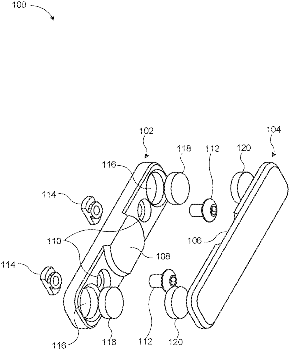
The patent describes a system for mounting accessories to firearms, featuring a mounting portion with an alignment projection and a recess for a mount-side object, along with an accessory portion designed to securely couple to the mounting portion. This configuration allows for easy attachment and detachment of accessories, enhancing the versatility of firearm setups.
Claim 1
1 . A system comprising: a mounting portion comprising: an alignment projection protruding from a first surface of the mounting portion; a mount-side recess formed in the first surface and offset from the alignment projection, wherein the mounting portion forms a through hole alongside the mount-side recess and extending through a thickness of the mounting portion; and a mount-side object disposed in the mount-side recess; and an accessory portion comprising: a second surface forming an alignment recess configured to receive the alignment projection of the mounting portion; an accessory-side recess formed in the second surface and offset from the alignment recess; and an accessory-side object disposed in the accessory-side recess, wherein the accessory-side object and the mount-side object are configured to couple to removably secure the accessory portion to the mounting portion. a mounting portion comprising: an alignment projection protruding from a first surface of the mounting portion; a mount-side recess formed in the first surface and offset from the alignment projection, wherein the mounting portion forms a through hole alongside the mount-side recess and extending through a thickness of the mounting portion; and a mount-side object disposed in the mount-side recess; and an alignment projection protruding from a first surface of the mounting portion; a mount-side recess formed in the first surface and offset from the alignment projection, wherein the mounting portion forms a through hole alongside the mount-side recess and extending through a thickness of the mounting portion; and a mount-side object disposed in the mount-side recess; and an accessory portion comprising: a second surface forming an alignment recess configured to receive the alignment projection of the mounting portion; an accessory-side recess formed in the second surface and offset from the alignment recess; and an accessory-side object disposed in the accessory-side recess, wherein the accessory-side object and the mount-side object are configured to couple to removably secure the accessory portion to the mounting portion. a second surface forming an alignment recess configured to receive the alignment projection of the mounting portion; an accessory-side recess formed in the second surface and offset from the alignment recess; and an accessory-side object disposed in the accessory-side recess, wherein the accessory-side object and the mount-side object are configured to couple to removably secure the accessory portion to the mounting portion.
Google Patents
https://patents.google.com/patent/US12716690
USPTO PDF
https://image-ppubs.uspto.gov/dirsearch-public/print/downloadPdf/12716690