US12704348 - Arrow rest device
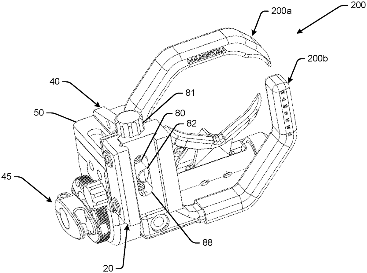
The patent describes an arrow rest device designed for archery bows, featuring a geometrically shaped mounting bracket and a coupler that allows for rotational adjustment of the archery accessory. The device includes a peg with a chamfered surface that facilitates self-alignment within the mounting bracket’s receiving feature, enhancing usability and stability during archery.
Claim 1
1 . An arrow rest device for an archery bow, comprising: a mounting bracket for connecting an archery accessory on a bow riser of the archery bow; a receiving feature formed as an opening in the mounting bracket for the archery accessory; a coupler mount for rotatably coupling onto the mounting bracket for the archery accessory; a peg attached on a first end portion to the coupler mount, the peg engaging with the receiving feature, in a first direction as the coupler mount is rotated in the first direction, and the peg engaging with the receiving feature in a second direction as the coupler mount is rotated in the second direction opposite to the first direction; a second end portion of the peg configured to slide into the receiving feature as the coupler mount is rotated in the first direction; and a chamfered surface of the second end portion of the peg configured to self-align the peg in the receiving feature, the chamfered surface forming a variable cross-section of the second end portion of the peg, wherein the variable cross-section of the peg is defined as having a circular shape prior to the chamfered surface and a partial circular shape with a chord along the chamfered surface, a length of the chord having a variable length from small to large and back to small as a resultant arc of the circumference continues to decrease. a mounting bracket for connecting an archery accessory on a bow riser of the archery bow; a receiving feature formed as an opening in the mounting bracket for the archery accessory; a coupler mount for rotatably coupling onto the mounting bracket for the archery accessory; a peg attached on a first end portion to the coupler mount, the peg engaging with the receiving feature, in a first direction as the coupler mount is rotated in the first direction, and the peg engaging with the receiving feature in a second direction as the coupler mount is rotated in the second direction opposite to the first direction; a second end portion of the peg configured to slide into the receiving feature as the coupler mount is rotated in the first direction; and a chamfered surface of the second end portion of the peg configured to self-align the peg in the receiving feature, the chamfered surface forming a variable cross-section of the second end portion of the peg, wherein the variable cross-section of the peg is defined as having a circular shape prior to the chamfered surface and a partial circular shape with a chord along the chamfered surface, a length of the chord having a variable length from small to large and back to small as a resultant arc of the circumference continues to decrease.
Google Patents
https://patents.google.com/patent/US12704348
USPTO PDF
https://image-ppubs.uspto.gov/dirsearch-public/print/downloadPdf/12704348