US12680794 - Bullet catcher target apparatus
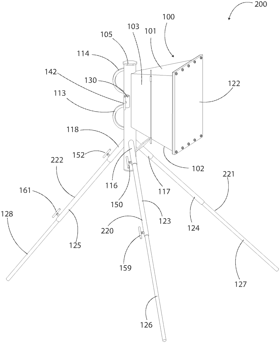
The bullet catcher target apparatus features a compact design with a tapered target enclosure that funnels bullets to a collector tube, enhancing safety and ease of use. It includes adjustable telescoping legs for versatile positioning on various terrains, making it portable and convenient for transport and storage.
Claim 1
1 . A bullet catcher target apparatus comprising: a target enclosure including a front opening opposite a rear, a bottom plate opposite a top plate, and two opposing side plates, the plates being angled such that the target enclosure tapers toward the rear thereof, thereby causing a bullet shot through the target enclosure to be funneled to the rear of the target enclosure; a front target wall attached to the front of the target enclosure, the front target wall being detachable from the target enclosure and made of self-healing ballistic rubber; an elongated cylindrical tube attached at the rear of the target enclosure as a collector tube configured to receive the bullet, stop momentum of the bullet and hold the bullet therein, the elongated cylindrical tube having a narrow elongated front opening through which the bullet is funneled, and including a bullet stop located inside the elongated cylindrical tube behind one of the side plates and configured to stop momentum of the bullet as it travels around a curvature of the elongated cylindrical tube, the elongated cylindrical tube further including a top cap and a bottom cap at each end thereof, and wherein the bottom cap is able to be moved, enabling removal of the bullet from the elongated cylindrical tube; at least three legs attached about the target enclosure, the at least three legs being independently height adjustable and movable between at least a prone position, a kneeling position and one or more standing positions; at least three leg sockets attached toward a bottom end of the elongated cylindrical tube wherein the at least three legs are each configured for insertion into one of the at least three leg sockets; and wherein the at least three leg sockets are configured to hold the at least three legs in the kneeling position and the one or more standing positions; and at least one handle attached to the target enclosure. a target enclosure including a front opening opposite a rear, a bottom plate opposite a top plate, and two opposing side plates, the plates being angled such that the target enclosure tapers toward the rear thereof, thereby causing a bullet shot through the target enclosure to be funneled to the rear of the target enclosure; a front target wall attached to the front of the target enclosure, the front target wall being detachable from the target enclosure and made of self-healing ballistic rubber; an elongated cylindrical tube attached at the rear of the target enclosure as a collector tube configured to receive the bullet, stop momentum of the bullet and hold the bullet therein, the elongated cylindrical tube having a narrow elongated front opening through which the bullet is funneled, and including a bullet stop located inside the elongated cylindrical tube behind one of the side plates and configured to stop momentum of the bullet as it travels around a curvature of the elongated cylindrical tube, the elongated cylindrical tube further including a top cap and a bottom cap at each end thereof, and wherein the bottom cap is able to be moved, enabling removal of the bullet from the elongated cylindrical tube; at least three legs attached about the target enclosure, the at least three legs being independently height adjustable and movable between at least a prone position, a kneeling position and one or more standing positions; at least three leg sockets attached toward a bottom end of the elongated cylindrical tube wherein the at least three legs are each configured for insertion into one of the at least three leg sockets; and wherein the at least three leg sockets are configured to hold the at least three legs in the kneeling position and the one or more standing positions; and at least one handle attached to the target enclosure.
Google Patents
https://patents.google.com/patent/US12680794
USPTO PDF
https://image-ppubs.uspto.gov/dirsearch-public/print/downloadPdf/12680794