US12644682 - Ignition device
The patent describes an ignition device that integrates an igniter and a holder, allowing the igniter to be inserted and secured through a press-fitting mechanism. The design includes a labyrinth structure and a tapered bore to enhance the sealing and stability of the ignition charge within the device.
Claim 1
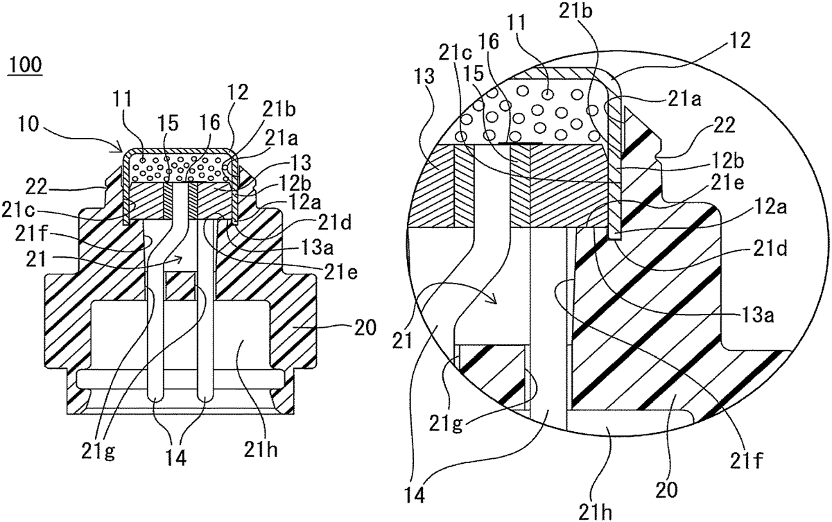
1 . An ignition device, comprising: an igniter that accommodates an ignition charge to be ignited by energization; and a holder that is integrated with the igniter by fitting the igniter into the holder, wherein the igniter includes: a tube body containing the ignition charge inside and including an opening, a header that occludes the opening and seals the ignition charge inside the tube body, and a pair of terminal pins provided on the header, an end portion of the tube body forming the opening and protruding with respect to the header, and the holder includes: a bore including an insertion port that is formed inside and into which the igniter is inserted and a press-fitting portion into which the tube body is press-fitted via the insertion port, the igniter being fitted into and fixed to the bore by press-fitting the tube body into the press-fitting portion via the insertion port, and an annular groove that is formed in a part of an inner wall of the bore and into which an end portion of the tube body is fitted, and a labyrinth structure formed by at least the end portion of the tube body fitted into the annular groove, wherein an opposite surface of the header on a side opposite to a side on which the ignition charge is disposed is in contact with a surface that is radially inner than the annular groove and is formed on an inner wall of the bore so as to face the opposite surface, wherein a tapered shape that reduces in diameter in a direction of the press-fitting is formed halfway from the surface that is radially inner than the annular groove and is formed on the inner wall of the bore so as to face the opposite surface to a portion of the bore where the pair of terminal pins is inserted on a side opposite to a side where the tube body is press-fitted. an igniter that accommodates an ignition charge to be ignited by energization; and a holder that is integrated with the igniter by fitting the igniter into the holder, wherein the igniter includes: a tube body containing the ignition charge inside and including an opening, a header that occludes the opening and seals the ignition charge inside the tube body, and a pair of terminal pins provided on the header, an end portion of the tube body forming the opening and protruding with respect to the header, and a tube body containing the ignition charge inside and including an opening, a header that occludes the opening and seals the ignition charge inside the tube body, and a pair of terminal pins provided on the header, an end portion of the tube body forming the opening and protruding with respect to the header, and the holder includes: a bore including an insertion port that is formed inside and into which the igniter is inserted and a press-fitting portion into which the tube body is press-fitted via the insertion port, the igniter being fitted into and fixed to the bore by press-fitting the tube body into the press-fitting portion via the insertion port, and an annular groove that is formed in a part of an inner wall of the bore and into which an end portion of the tube body is fitted, and a labyrinth structure formed by at least the end portion of the tube body fitted into the annular groove, wherein an opposite surface of the header on a side opposite to a side on which the ignition charge is disposed is in contact with a surface that is radially inner than the annular groove and is formed on an inner wall of the bore so as to face the opposite surface, wherein a tapered shape that reduces in diameter in a direction of the press-fitting is formed halfway from the surface that is radially inner than the annular groove and is formed on the inner wall of the bore so as to face the opposite surface to a portion of the bore where the pair of terminal pins is inserted on a side opposite to a side where the tube body is press-fitted. a bore including an insertion port that is formed inside and into which the igniter is inserted and a press-fitting portion into which the tube body is press-fitted via the insertion port, the igniter being fitted into and fixed to the bore by press-fitting the tube body into the press-fitting portion via the insertion port, and an annular groove that is formed in a part of an inner wall of the bore and into which an end portion of the tube body is fitted, and a labyrinth structure formed by at least the end portion of the tube body fitted into the annular groove, wherein an opposite surface of the header on a side opposite to a side on which the ignition charge is disposed is in contact with a surface that is radially inner than the annular groove and is formed on an inner wall of the bore so as to face the opposite surface, wherein a tapered shape that reduces in diameter in a direction of the press-fitting is formed halfway from the surface that is radially inner than the annular groove and is formed on the inner wall of the bore so as to face the opposite surface to a portion of the bore where the pair of terminal pins is inserted on a side opposite to a side where the tube body is press-fitted.
Google Patents
https://patents.google.com/patent/US12644682
USPTO PDF
https://image-ppubs.uspto.gov/dirsearch-public/print/downloadPdf/12644682