US12624925 - Hinged scope ring
The patent describes a hinged scope ring designed to attach a rifle scope to a mounting rail, featuring an upper component that can pivot open for easy scope insertion or removal while maintaining a slim profile. This scope ring allows for adjustable heights by enabling different compatible lower components to be attached to the upper component.
Claim 1
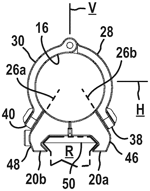
1 . A scope ring for attaching a scope to a mounting rail of an armament, the scope ring comprising: a scope ring through-hole being configured to receive a portion of the scope; an upper component and a lower component, the lower component having a first end portion on a first end of the lower component and an axially opposite second end portion, the first end portion being capable of being attached onto the mounting rail whereby the second end portion is spaced away from the mounting rail when the lower component is mounted on the rail; the upper component being fastenable to the second end portion of the lower component to rigidly attach the upper component to the lower component wherein the upper component and the second end portion of the lower component cooperate to surround and define the scope ring through-hole when the upper component is fastened to the lower component; the upper component comprising a first end and a second end, the first and second ends of the upper component being spaced apart from one another and each of the first and second ends being fixedly fastened to the lower component when the upper component is attached to the lower component; the upper component comprising at least two members that extend end-to-end along and define a portion of an outer perimeter of the scope ring through-hole from the first end of the upper component to the second end of the upper component when the upper component is fastened to the lower component, the at least two members comprising at least one adjacent pair of members extending along the outer perimeter; each adjacent pair of members of the at least one adjacent pair of members comprising respective adjacent ends that cooperatively define a hinge that pivotally couples the adjacent pairs of members, the hinge receiving a hinge pin that defines the pivot axis of the hinge, the hinge enabling pivotal movement of the adjacent pair of members about the hinge axis when one or both ends of the upper component is unfastened from the lower component; the at least two members of the upper component extending more than one hundred and eighty (180) degrees in angular extent along the outer perimeter of the scope ring through-hole from the first end of the upper component to the second end of the upper component when the upper component is fastened to the lower component; and wherein the upper component and the lower component when attached together with the lower component attached onto the mounting rail define a first scope ring height, the scope ring comprising at least one additional lower component attachable to the upper component to define the scope ring through-hole, each at least one additional lower component defining a respective scope ring height in cooperation with the upper component that is different from the first scope ring height and different from the scope ring height defined by any other of the at least one additional lower component in cooperation with the upper component. a scope ring through-hole being configured to receive a portion of the scope; an upper component and a lower component, the lower component having a first end portion on a first end of the lower component and an axially opposite second end portion, the first end portion being capable of being attached onto the mounting rail whereby the second end portion is spaced away from the mounting rail when the lower component is mounted on the rail; the upper component being fastenable to the second end portion of the lower component to rigidly attach the upper component to the lower component wherein the upper component and the second end portion of the lower component cooperate to surround and define the scope ring through-hole when the upper component is fastened to the lower component; the upper component comprising a first end and a second end, the first and second ends of the upper component being spaced apart from one another and each of the first and second ends being fixedly fastened to the lower component when the upper component is attached to the lower component; the upper component comprising at least two members that extend end-to-end along and define a portion of an outer perimeter of the scope ring through-hole from the first end of the upper component to the second end of the upper component when the upper component is fastened to the lower component, the at least two members comprising at least one adjacent pair of members extending along the outer perimeter; each adjacent pair of members of the at least one adjacent pair of members comprising respective adjacent ends that cooperatively define a hinge that pivotally couples the adjacent pairs of members, the hinge receiving a hinge pin that defines the pivot axis of the hinge, the hinge enabling pivotal movement of the adjacent pair of members about the hinge axis when one or both ends of the upper component is unfastened from the lower component; the at least two members of the upper component extending more than one hundred and eighty (180) degrees in angular extent along the outer perimeter of the scope ring through-hole from the first end of the upper component to the second end of the upper component when the upper component is fastened to the lower component; and wherein the upper component and the lower component when attached together with the lower component attached onto the mounting rail define a first scope ring height, the scope ring comprising at least one additional lower component attachable to the upper component to define the scope ring through-hole, each at least one additional lower component defining a respective scope ring height in cooperation with the upper component that is different from the first scope ring height and different from the scope ring height defined by any other of the at least one additional lower component in cooperation with the upper component.
Google Patents
https://patents.google.com/patent/US12624925
USPTO PDF
https://image-ppubs.uspto.gov/dirsearch-public/print/downloadPdf/12624925