US12624922 - LED emergent light adjusting mechanism and inner-red-dot aiming device therefor
The patent describes an LED emergent light adjusting mechanism designed for an inner-red-dot aiming device, featuring both vertical and horizontal adjustment assemblies that utilize various spring and sliding components for precise alignment. The LED chip assembly includes a central point light source and an annular light source, enhancing the aiming device’s functionality.
Claim 1
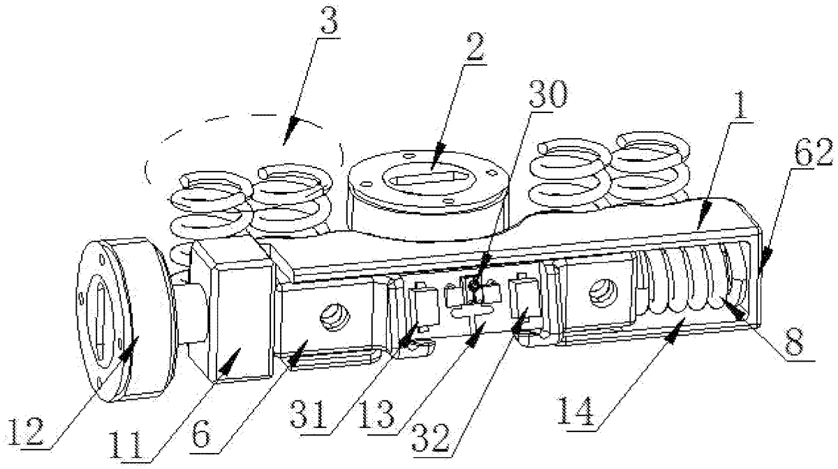
1 . An LED emergent light adjusting mechanism, comprising a vertical adjusting assembly and a horizontal adjusting assembly, wherein the vertical adjusting assembly comprises an up-and-down adjusting sliding block, a vertical adjustment screw, and two vertical adjustment spring sets which are respectively arranged on two sides of the vertical adjustment screw and are symmetrical with respect to the vertical adjustment screw; a nut member fixed at a middle portion of a bottom side at a rear end of the up-and-down adjusting sliding block for threadedly connecting with a bolt of the vertical adjustment screw; two guiding and limiting column sets symmetrically provided on two sides of the nut member for sleeving the vertical adjustment spring sets thereon, a base of each guiding and limiting column set being fixedly connected with the bottom side at the rear end of the up-and-down adjusting sliding block; the horizontal adjusting assembly comprises a left-and-right sliding block, a return spring having one end sleeved on a limiting protrusion at one end portion of the left-and-right sliding block, two vertical spring ejector pin assemblies symmetrically arranged on a top surface of the left-and-right sliding block, two horizontal spring ejector pin assemblies symmetrically arranged at a rear end of the left-and-right sliding block, a horizontal adjustment screw coupled to another end of the left-and-right sliding block through a square nut, and an LED chip assembly arranged on a front end surface of the left-and-right sliding block; a mounting groove is provided on a front end surface of the up-and-down adjusting sliding block, the left-and-right sliding block is placed in the mounting groove, and the return spring is placed between the left-and-right sliding block and a baffle plate fixed at an end portion of the mounting groove; the square nut is placed outside another end portion of the mounting groove; each vertical spring ejector pin assembly is placed between the top surface of the left-and-right sliding block and a top wall of the mounting groove to eliminate a mounting gap in a vertical direction of the left-and-right sliding block; each horizontal spring ejector pin assembly is placed between the rear end of the left-and-right sliding block and a side wall of the mounting groove to eliminate a mounting gap in a front-and-rear direction of the left-and-right sliding block; the LED chip assembly comprises an LED light source composed of a central point light source and a discontinuous annular light source surrounding around the central point light source. a nut member fixed at a middle portion of a bottom side at a rear end of the up-and-down adjusting sliding block for threadedly connecting with a bolt of the vertical adjustment screw; two guiding and limiting column sets symmetrically provided on two sides of the nut member for sleeving the vertical adjustment spring sets thereon, a base of each guiding and limiting column set being fixedly connected with the bottom side at the rear end of the up-and-down adjusting sliding block; the horizontal adjusting assembly comprises a left-and-right sliding block, a return spring having one end sleeved on a limiting protrusion at one end portion of the left-and-right sliding block, two vertical spring ejector pin assemblies symmetrically arranged on a top surface of the left-and-right sliding block, two horizontal spring ejector pin assemblies symmetrically arranged at a rear end of the left-and-right sliding block, a horizontal adjustment screw coupled to another end of the left-and-right sliding block through a square nut, and an LED chip assembly arranged on a front end surface of the left-and-right sliding block; a mounting groove is provided on a front end surface of the up-and-down adjusting sliding block, the left-and-right sliding block is placed in the mounting groove, and the return spring is placed between the left-and-right sliding block and a baffle plate fixed at an end portion of the mounting groove; the square nut is placed outside another end portion of the mounting groove; each vertical spring ejector pin assembly is placed between the top surface of the left-and-right sliding block and a top wall of the mounting groove to eliminate a mounting gap in a vertical direction of the left-and-right sliding block; each horizontal spring ejector pin assembly is placed between the rear end of the left-and-right sliding block and a side wall of the mounting groove to eliminate a mounting gap in a front-and-rear direction of the left-and-right sliding block; the LED chip assembly comprises an LED light source composed of a central point light source and a discontinuous annular light source surrounding around the central point light source.
Google Patents
https://patents.google.com/patent/US12624922
USPTO PDF
https://image-ppubs.uspto.gov/dirsearch-public/print/downloadPdf/12624922