US12618637 - Muzzle loader
The patent describes a muzzle-loading system that incorporates a ramrod and a muzzle loader designed to provide feedback when a target loading pressure is achieved. The system features an enclosure with a plunger and cam mechanism that allows for controlled loading of the firearm while preventing rotation of the components.
Claim 1
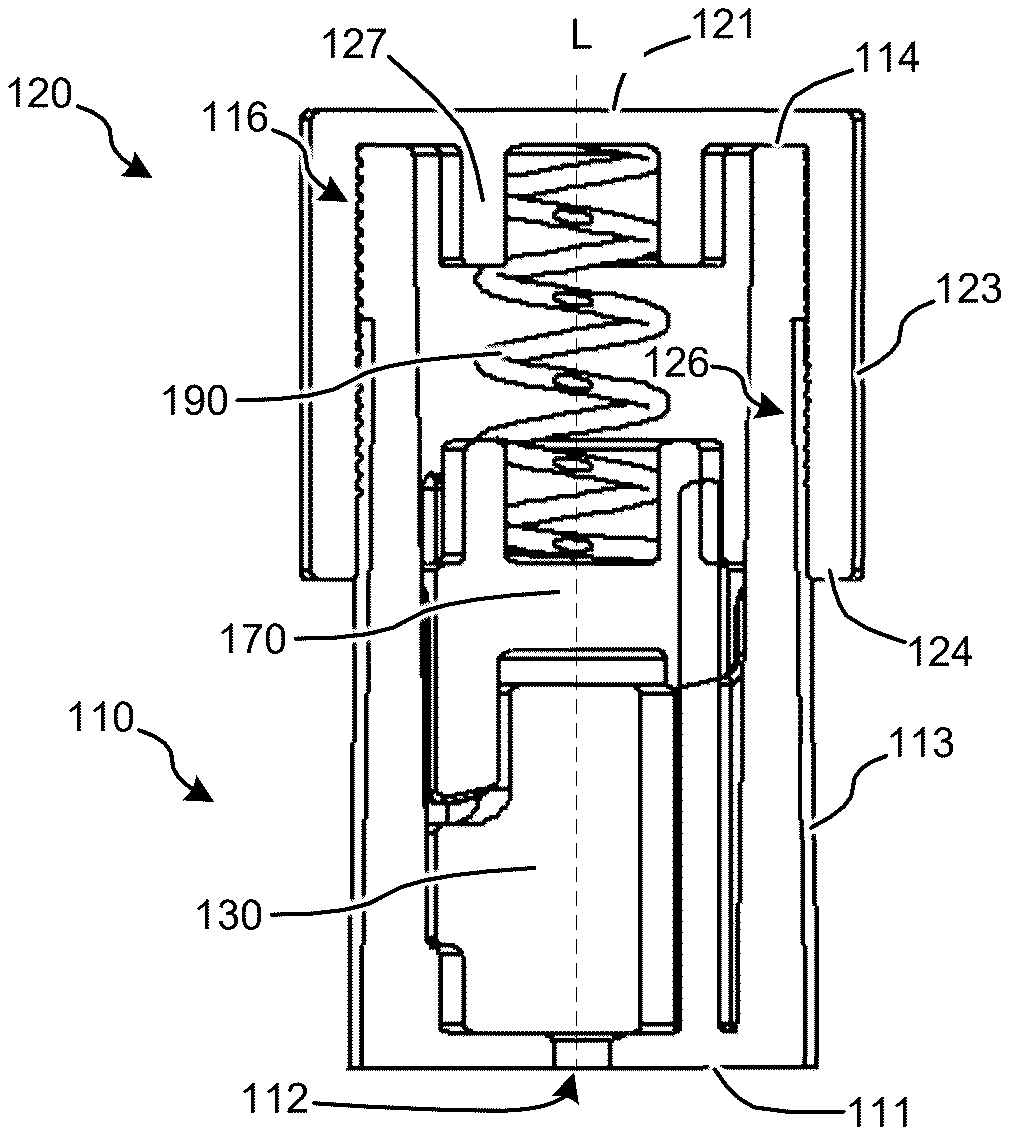
1 . A muzzle loader for muzzle-loading a firearm, comprising: an enclosure comprising an enclosure top side, an enclosure bottom side, one or more guides between the enclosure top side and the enclosure bottom side, and a ramrod receiving port through the enclosure bottom side; a plunger in the enclosure, the plunger comprising a plunger top side, a plunger bottom side, and a ramrod seat along the plunger bottom side; a cam comprising a cam top side, a cam bottom side, and one or more radially-inclined surfaces along the cam bottom side; and one or more springs between the enclosure top side and the cam top side that bias the plunger and the cam toward the enclosure bottom side; wherein the one or more guides engage the plunger and the cam and prevent rotation of the plunger and the cam within the enclosure; wherein the plunger and the cam are configured to move longitudinally toward the enclosure top side in response to pressure applied to the plunger via the ramrod receiving port; and wherein the cam is configured to rotate and partially release the pressure applied to the plunger in response to the pressure applied to plunger reaching a target loading pressure. an enclosure comprising an enclosure top side, an enclosure bottom side, one or more guides between the enclosure top side and the enclosure bottom side, and a ramrod receiving port through the enclosure bottom side; a plunger in the enclosure, the plunger comprising a plunger top side, a plunger bottom side, and a ramrod seat along the plunger bottom side; a cam comprising a cam top side, a cam bottom side, and one or more radially-inclined surfaces along the cam bottom side; and one or more springs between the enclosure top side and the cam top side that bias the plunger and the cam toward the enclosure bottom side; wherein the one or more guides engage the plunger and the cam and prevent rotation of the plunger and the cam within the enclosure; wherein the plunger and the cam are configured to move longitudinally toward the enclosure top side in response to pressure applied to the plunger via the ramrod receiving port; and wherein the cam is configured to rotate and partially release the pressure applied to the plunger in response to the pressure applied to plunger reaching a target loading pressure.
Google Patents
https://patents.google.com/patent/US12618637
USPTO PDF
https://image-ppubs.uspto.gov/dirsearch-public/print/downloadPdf/12618637