US12618634 - Muzzle flash simulator and method for generating light trail
The patent describes a muzzle flame simulator designed for toy air guns, which generates a light trail through a combination of a projectile sensor, a controller, and multiple illuminating components that emit light of varying colors and intensities. The system activates upon detecting a projectile, utilizing preset control signals to create a realistic visual effect that simulates a muzzle flash.
Claim 1
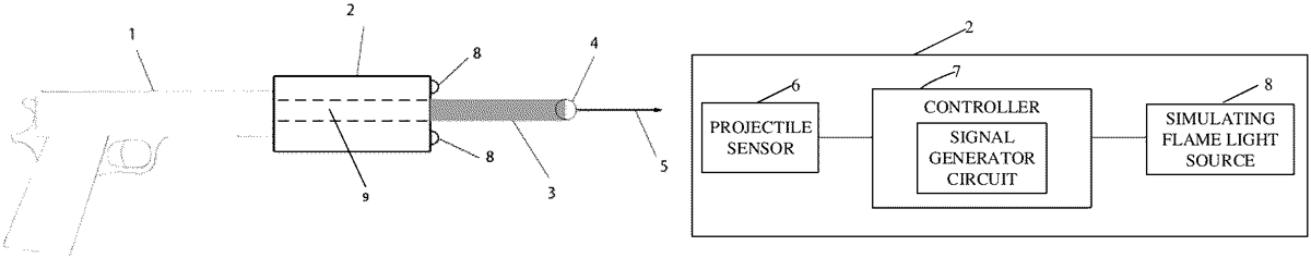
1 . A muzzle flame simulator, wherein the muzzle flame simulator is installed at a muzzle of a toy air gun, comprising: a projectile passage disposed inside the muzzle flame simulator, the projectile passage being coaxial with a projectile flight trajectory; a projectile sensor coupled to a controller and configured to send a trigger signal to the controller in response to detecting a projectile passing through the projectile passage; the controller comprising a signal generator circuit, wherein the signal generator circuit is configured to output at least two preset periodically changing control signals, and the at least two preset periodically changing control signals are respectively configured to control brightness, an on state, and an off state of at least two illuminating components with different colors; and the signal generator circuit is a digital signal generator circuit or an analog signal generator circuit; and at least one simulating flame light source coupled to the controller, wherein the at least one simulating flame light source each comprises the at least two illuminating components with different colors, and the at least two illuminating components are configured to periodically emit light of different colors and different intensities to the projectile based on the at least two preset periodically changing control signals, the light of different colors and different intensities are used to form a corresponding light trail based on a projectile flight trajectory; wherein the controller is configured to start the signal generator circuit in response to detecting the trigger signal sent by the projectile sensor to enable the signal generator circuit to output the at least two preset periodically changing control signals and further enable the at least two illuminating components with different colors periodically emit light of different colors and intensities to the projectile based on the at least two preset periodically changing control signals; wherein for each of the at least two preset periodically changing control signals, the control signal contains a positive voltage signal, a duration of the positive voltage signal is calculated by a formula: a projectile passage disposed inside the muzzle flame simulator, the projectile passage being coaxial with a projectile flight trajectory; a projectile sensor coupled to a controller and configured to send a trigger signal to the controller in response to detecting a projectile passing through the projectile passage; the controller comprising a signal generator circuit, wherein the signal generator circuit is configured to output at least two preset periodically changing control signals, and the at least two preset periodically changing control signals are respectively configured to control brightness, an on state, and an off state of at least two illuminating components with different colors; and the signal generator circuit is a digital signal generator circuit or an analog signal generator circuit; and at least one simulating flame light source coupled to the controller, wherein the at least one simulating flame light source each comprises the at least two illuminating components with different colors, and the at least two illuminating components are configured to periodically emit light of different colors and different intensities to the projectile based on the at least two preset periodically changing control signals, the light of different colors and different intensities are used to form a corresponding light trail based on a projectile flight trajectory; wherein the controller is configured to start the signal generator circuit in response to detecting the trigger signal sent by the projectile sensor to enable the signal generator circuit to output the at least two preset periodically changing control signals and further enable the at least two illuminating components with different colors periodically emit light of different colors and intensities to the projectile based on the at least two preset periodically changing control signals; wherein for each of the at least two preset periodically changing control signals, the control signal contains a positive voltage signal, a duration of the positive voltage signal is calculated by a formula: 3 T 2 n T represents a period of the control signal, T is less than 0.1 seconds, n represents the number of colors of the illuminating components, and n is greater than 1; wherein a phase difference between two adjacent control signals among the at least two preset periodically changing control signals is calculated by a formula: T represents a period of the control signal, T is less than 0.1 seconds, n represents the number of colors of the illuminating components, and n is greater than 1; wherein a phase difference between two adjacent control signals among the at least two preset periodically changing control signals is calculated by a formula: 360 ° n .
Google Patents
https://patents.google.com/patent/US12618634
USPTO PDF
https://image-ppubs.uspto.gov/dirsearch-public/print/downloadPdf/12618634