US12595981 - Braking mechanism for a gun
The patent describes a braking mechanism for firearms that utilizes a fork structure with brake rollers and vertical engagement grooves in the breech to control the braking state. It incorporates spring-loaded pins, supporting pins, and a locking lever to enhance safety and functionality during operation.
Claim 1
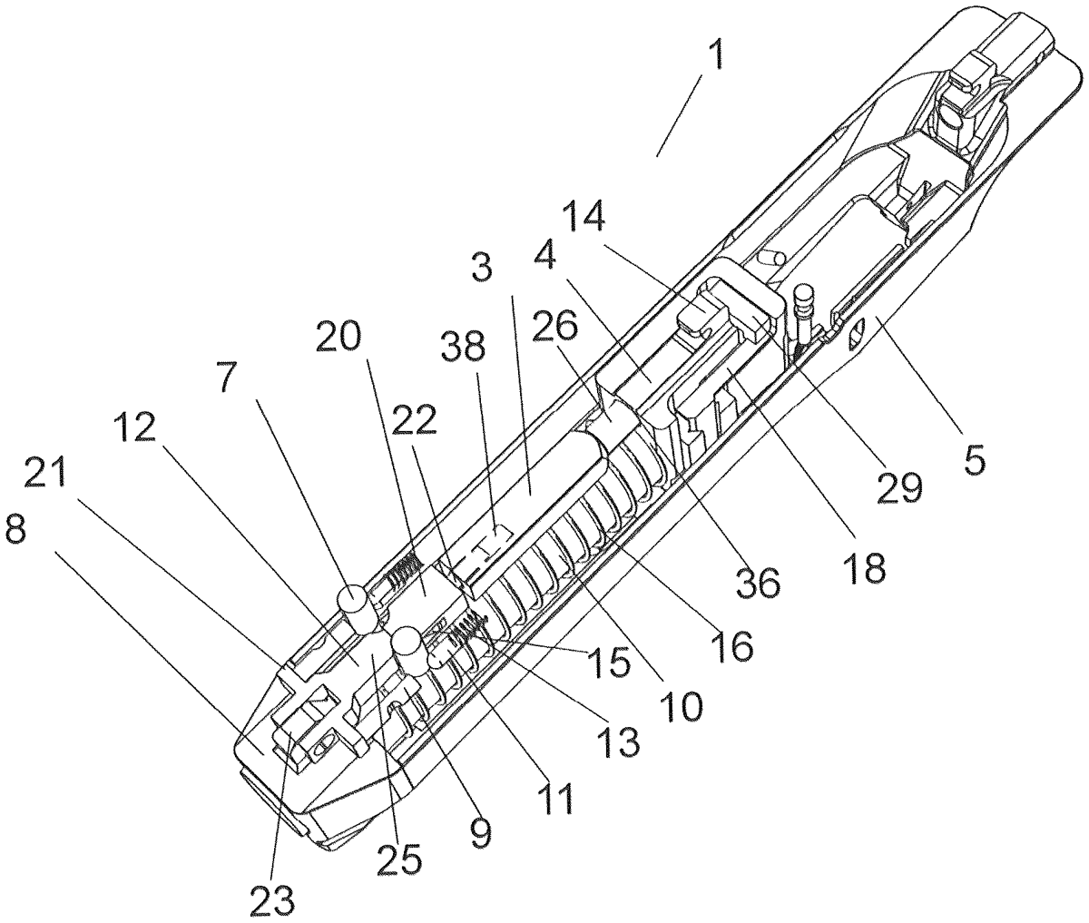
1 . Braking mechanism for a gun arranged in a frame and breech of a gun, the frame being provided with a cavity in which a barrel is arranged, comprising: a fork deposited on an upper projection on a head of a frame via a pin; arms projecting laterally from a respective side of the fork; brake rollers; vertical engagement grooves each for receiving a respective one of the brake rollers in a braking state provided on a flank of the breech of the gun, each vertical engagement groove being a part of a vertical shaped groove arranged in an upper wall of the breech for full or partial reception of the respective one of the brake rollers, depending on whether the braking mechanism is in a rest or a braking position; spring-loaded pins each arranged at one side of a respective one of the brake roller to press the respective one of the brake roller into a respective one of the vertical shaped grooves in the rest position of the braking mechanism, each spring-loaded pin being associated with a respective compression spring for urging the spring-loaded pin against the respective one of the brake rollers; supporting pins each abutting a respective one of the arms at one side thereof and abutting another side of a respective one of the brake roller at another side thereof to support the respective one of the brake roller during braking; breech bushings on both sides of a front part of the breech in which concentric longitudinal front and rear cavities are provided opposite each other, the front cavity in each breech bushing being open and accommodating a respective one of the supporting pins and the rear cavity in each breech bushing being closed and accommodating a respective one of the spring-loaded pins, the front and rear cavities of each breech bushing being separated on an inner wall of the breech bushing by a gap, thereby dividing the inner wall of the front and rear cavities thereof into a front branch and a rear branch, an inner face of the front branch thereof being on an edge facing the front and rear cavities thereof; an engagement chamfer provided at each front branch for abutting a respective one of the brake rollers during braking; a tapered tongue terminating a body of the fork for controlling a position of the brake rollers in the shaped grooves; circular recesses to receive brake rollers in the rest position of the mechanism; a fork rod that passes into the sleeve cavity of a sleeve and is arranged behind the tapered tongue, the sleeve cavity being longer than the fork rod; an end rod provided at another end of the sleeve, which is inserted into a through opening in a base, the base being a shaped block an substantially as wide as the cavity of the frame; a cylindrical ending at a face of the end rod arranged eccentrically below a center of the end rod; and a locking lever of a control arm for actuating the braking mechanism placed in front of a trigger, the control arm being provided with a control arm groove for inserting a connecting lever, which is connected at an end thereof to the locking lever and, at an opposite end thereof, the control arm is provided with a transverse beam for blocking the end rod, which is accommodated above an ending of the end rod, wherein each brake roller is inserted into the shaped groove, which is bounded on one side by a tongue and on another side by an engagement groove, and wherein each supporting pin is provided with a vertical elongated groove for accommodating a safety pin for stopping movement of the supporting pin during braking, while a remaining half of each safety pin is placed in a vertical groove arranged in a side of the breech. a fork deposited on an upper projection on a head of a frame via a pin; arms projecting laterally from a respective side of the fork; brake rollers; vertical engagement grooves each for receiving a respective one of the brake rollers in a braking state provided on a flank of the breech of the gun, each vertical engagement groove being a part of a vertical shaped groove arranged in an upper wall of the breech for full or partial reception of the respective one of the brake rollers, depending on whether the braking mechanism is in a rest or a braking position; spring-loaded pins each arranged at one side of a respective one of the brake roller to press the respective one of the brake roller into a respective one of the vertical shaped grooves in the rest position of the braking mechanism, each spring-loaded pin being associated with a respective compression spring for urging the spring-loaded pin against the respective one of the brake rollers; supporting pins each abutting a respective one of the arms at one side thereof and abutting another side of a respective one of the brake roller at another side thereof to support the respective one of the brake roller during braking; breech bushings on both sides of a front part of the breech in which concentric longitudinal front and rear cavities are provided opposite each other, the front cavity in each breech bushing being open and accommodating a respective one of the supporting pins and the rear cavity in each breech bushing being closed and accommodating a respective one of the spring-loaded pins, the front and rear cavities of each breech bushing being separated on an inner wall of the breech bushing by a gap, thereby dividing the inner wall of the front and rear cavities thereof into a front branch and a rear branch, an inner face of the front branch thereof being on an edge facing the front and rear cavities thereof; an engagement chamfer provided at each front branch for abutting a respective one of the brake rollers during braking; a tapered tongue terminating a body of the fork for controlling a position of the brake rollers in the shaped grooves; circular recesses to receive brake rollers in the rest position of the mechanism; a fork rod that passes into the sleeve cavity of a sleeve and is arranged behind the tapered tongue, the sleeve cavity being longer than the fork rod; an end rod provided at another end of the sleeve, which is inserted into a through opening in a base, the base being a shaped block an substantially as wide as the cavity of the frame; a cylindrical ending at a face of the end rod arranged eccentrically below a center of the end rod; and a locking lever of a control arm for actuating the braking mechanism placed in front of a trigger, the control arm being provided with a control arm groove for inserting a connecting lever, which is connected at an end thereof to the locking lever and, at an opposite end thereof, the control arm is provided with a transverse beam for blocking the end rod, which is accommodated above an ending of the end rod, wherein each brake roller is inserted into the shaped groove, which is bounded on one side by a tongue and on another side by an engagement groove, and wherein each supporting pin is provided with a vertical elongated groove for accommodating a safety pin for stopping movement of the supporting pin during braking, while a remaining half of each safety pin is placed in a vertical groove arranged in a side of the breech.
Google Patents
https://patents.google.com/patent/US12595981
USPTO PDF
https://image-ppubs.uspto.gov/dirsearch-public/print/downloadPdf/12595981