Mar 3, 2026
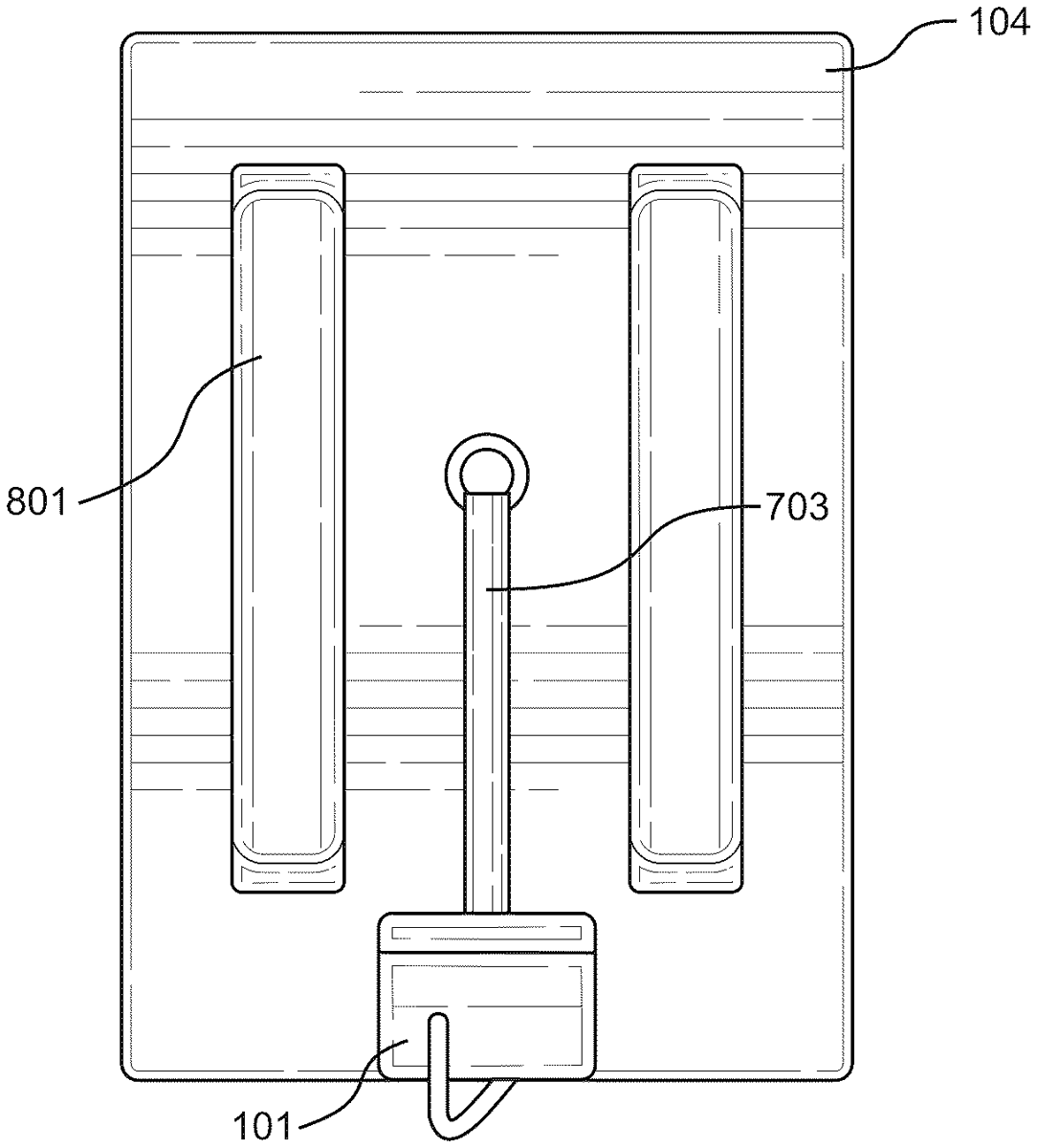
An underlap stabilizing stand including a holder structured to support an elongate object therein, an upper swivel, a base, a lower swivel, and a longitudinal support between the holder and the base. The holder is connected to the longitudinal support via the upper swivel and the base is connected to the longitudinal support via the lower swivel. The underlap stabilizing stand is structured to stabilize, position and aim the elongate object along x, y, and z axes of the underlap stabilizing stand.
Mar 3, 2026
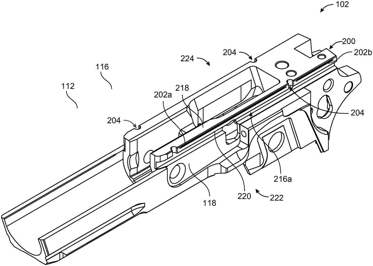
A firearm with a slide and a frame. The slide has a slide rail. The frame has a frame rail. The frame rail interfaces with the slide rail. The frame rail has a lubrication groove and a debris removal port. The lubrication groove extends along a surface of the frame rail that bears against the slide rail during operation of the firearm. The debris removal port has gap within the frame rail proximate to an end of the lubrication groove.
Mar 3, 2026
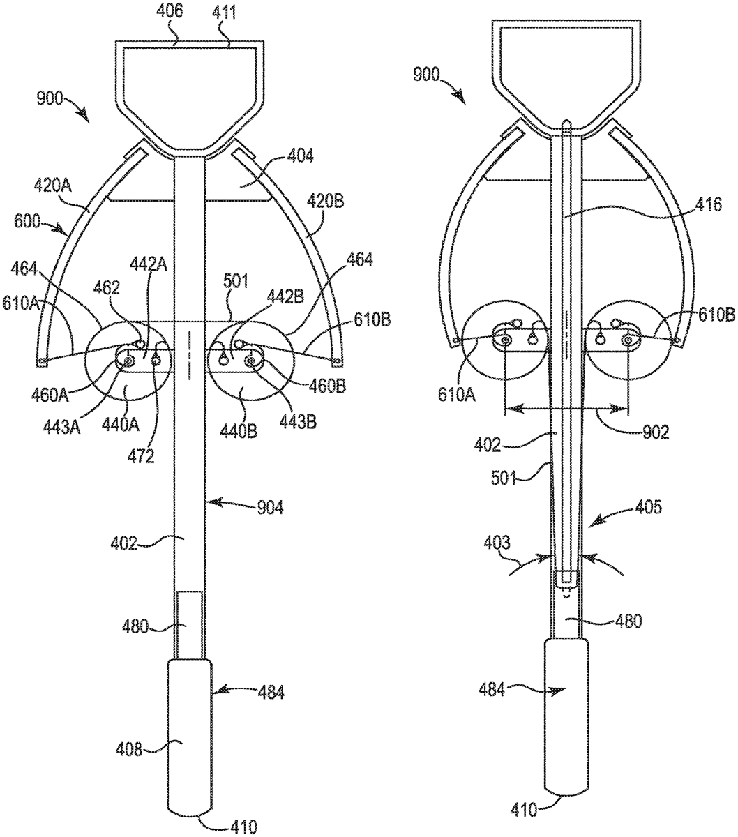
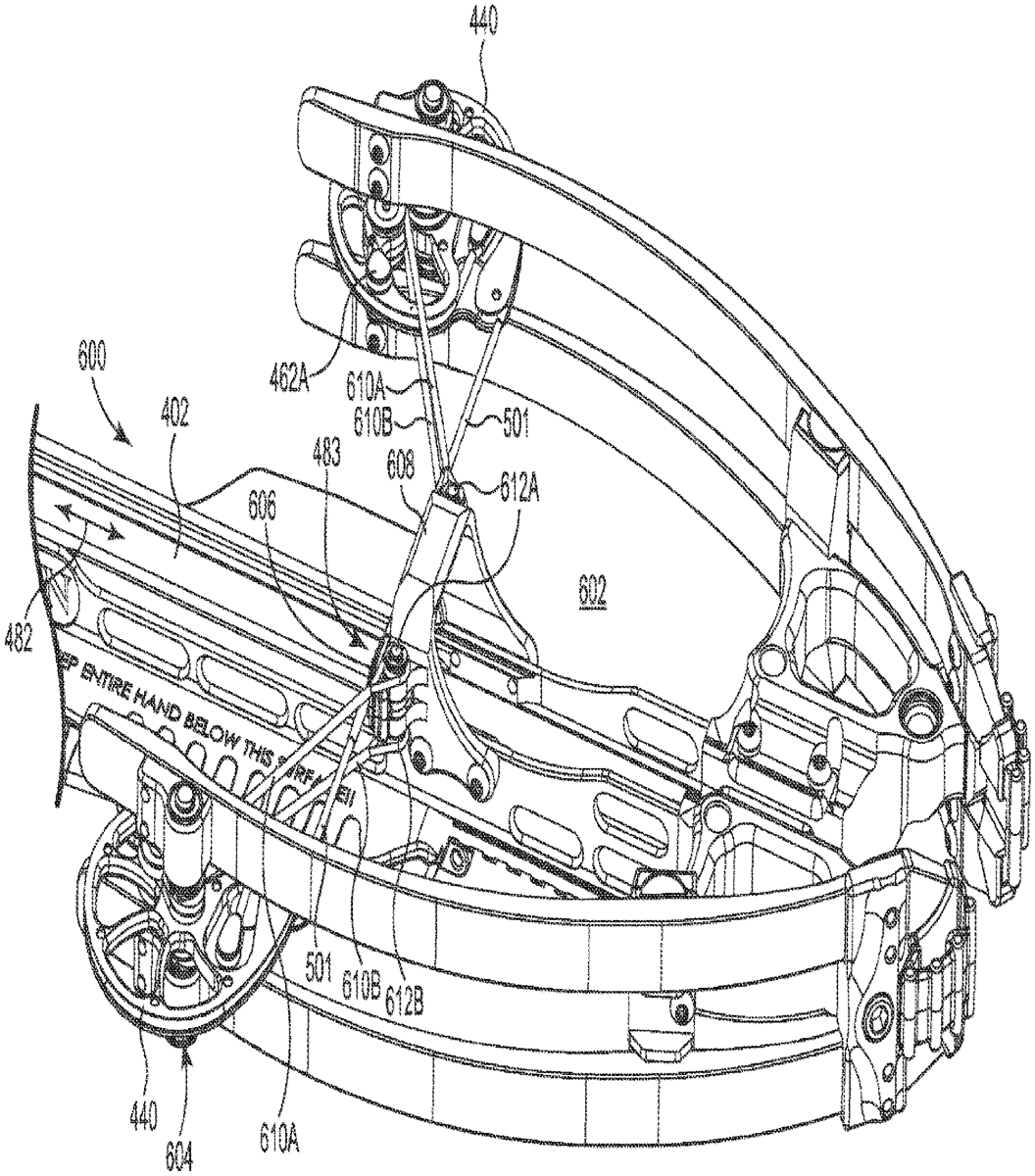
A crossbow including a frame with a riser and a center rail. First and second flexible limbs are attached to the riser. A draw string is received in string guide journals in first and second cams rotatably attached to the frame. The draw string unwinds from the string guide journals as it translates between a released configuration and a drawn configuration. The first and second cams include at least first and second power cable take-up journals, respectively. At least first and second power cables are attached to the first and second limbs and received in the first and second power cable take-up journals, respectively. As the crossbow is drawn from the released configuration to the drawn configuration the first and second power cables wrap onto the respective first and second power cable take-up journals.
Mar 3, 2026
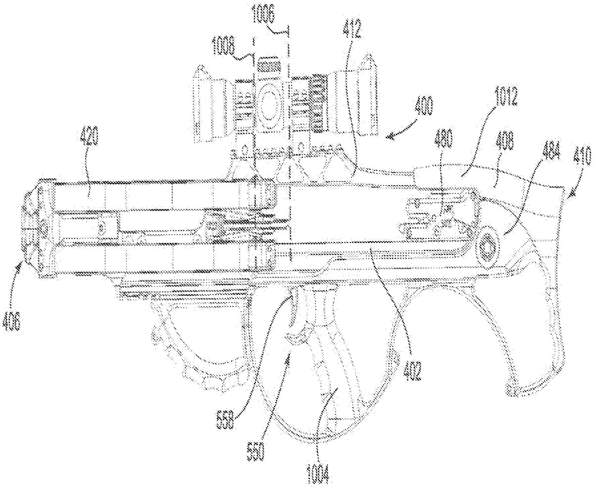
A crossbow including a center rail including a bottom portion, a proximal end, and a distal end positioned opposite the proximal end, the center rail at least partially defining a crossbow length and a midpoint plane intersecting a horizontal midpoint of the crossbow, a riser extending horizontally from the distal end, one or more limbs coupled to the riser, and a trigger extending from the bottom portion of the center rail and positioned within ten percent of the crossbow length from the midpoint plane.
Mar 3, 2026
A crossbow string guides that include upper and lower helical power cable journals on opposite sides of a draw string journal. A separation between first and second axis of the string guides in a drawn configuration is about 5 inches to about 10 inches and the draw string in the drawn configuration comprises an included angle of less than about 25 degrees. First and second pairs of power cables wrap and unwrap at least 300 degrees around, the respective first and second upper and lower helical power cable journals as the draw string moves between a released configuration to a drawn configuration.
Mar 3, 2026
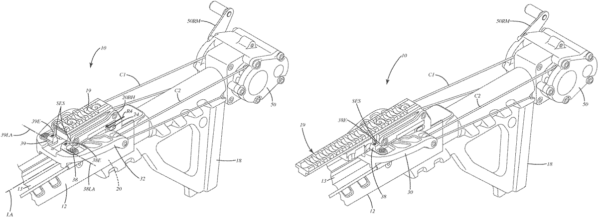
A crossbow can include a de-cocking system to allow a bowstring to be transitioned from a drawn mode to an undrawn mode. The de-cocking system can include a sled that engages the bowstring to draw it to a drawn mode and/or lets down the bowstring to the undrawn mode during a de-cocking operation. The sled can include a stop that prevents the sled or bowstring from engaging a safety and/or interfering with transition of the safety from a safety on mode to a safety off mode. The safety can be manually actuated from the safety on mode to the safety off mode. With the safety in the off mode, upon actuation of a trigger assembly, the sled assists transition of the bowstring to the undrawn mode. The stop can be reconfigured to a neutral mode so the sled can be used to draw the bowstring. A related method is provided.
Mar 3, 2026
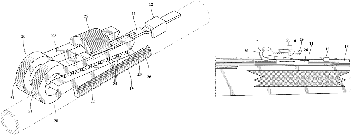
A rear firearm sight slide elevator with a base member that is configured to surround a part of a firearm barrel and first and second clips that are situated on top of the base member and parallel to each other, with the first clip situated along a first side of the base member and the second clip situated on a second side of the base member. Each clip has a top part in the form of an elongated member, a bottom part in the form of an elongated ramp, and a hinge that connects the top part to the bottom part at a rear end of the clip. The elongated member includes a plurality of teeth that extend downwardly from a bottom surface of the elongated member. The hinge may be rounded or rectangular in shape.
Mar 3, 2026
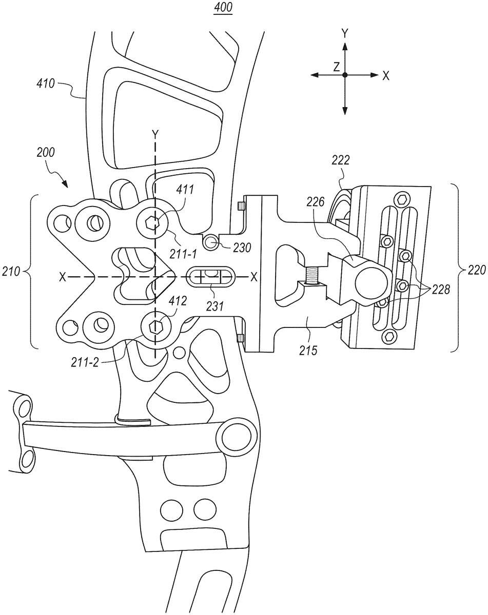
Archery bow risers and bow accessories are provided which comprise integrated level devices for use in, e.g., tuning and installing accessories on archery bows such as compound bows. For example, a bow sight device comprises a mounting bracket configured for attachment to a bow riser, and a sight housing adjustably connected to the mounting bracket. The mounting bracket comprises a first level device and a second level device. The first level device is configured to enable a user to level the bow riser in a first direction, when the bow sight device is attached to the bow riser. The second level device is configured to enable a user to level the bow riser and the sight housing in a second direction which is orthogonal to the first direction, when the bow sight device is attached to the bow riser.
Mar 3, 2026
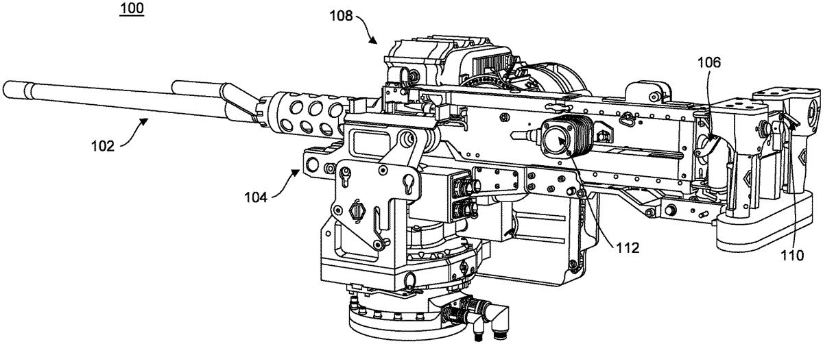
The devices, systems, and methods described herein are directed to a manual and assisted targeting system integrated into a weapon control system that includes dual triggers. One trigger is fully manual and is always operational. The second trigger is electronically controlled and is linked to aiming sensors, targeting sensors, and a controller comprising firing control logic. The firing control logic calculates an aim goal, based at least partially on location information pertaining to the target, and determines when the difference between the aimpoint of the weapon and the aim goal is below a threshold. In response to this determination, a control signal is sent to a trigger actuator to fire the weapon.
Mar 3, 2026
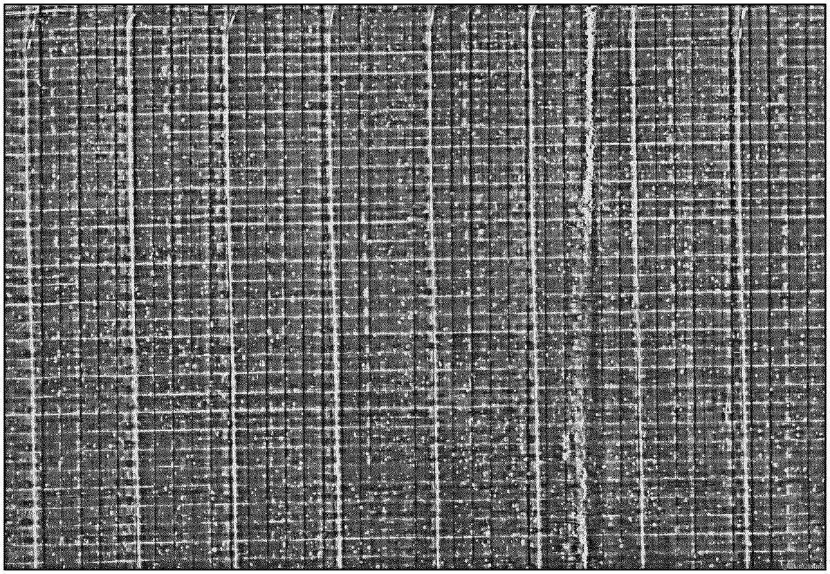
Ballistic resistant composite materials having high positive buoyancy in water are provided. More particularly, provided are foam-free, buoyant composite materials fabricated using dry processing techniques. The materials comprise fibrous plies that are partially coated with a particulate binder that is thermopressed to transform a portion of the binder into raised, discontinuous patches bonded to fiber/tape surfaces, while another portion of the particulate binder remains on the fibers/tapes as unmelted particles. The presence of the unmelted binder particles maintains empty spaces within the composite materials which increases the positive buoyancy of the composites in water.
Mar 3, 2026
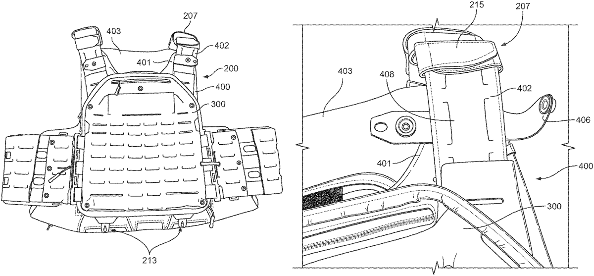
An armor carrier comprises a plate bag removably attachable to a soft armor carrier. The soft armor carrier comprises at least one panel and, in some cases, a front panel, a rear panel, and a pair of shoulder straps. The pair of shoulder straps may include one or more spaced-apart slit openings in a patterned configuration, and the front and rear panels of the soft armor carrier include one or more spaced-apart slit openings in a horizontal or vertical orientation. The plate bag, which comprises a front panel, a rear panel, and a pair of shoulder straps corresponding with respective components of the soft armor carrier, is donned over the soft armor carrier. The plate bag is removably secured to the soft armor carrier via one or more attachment fittings disposed on the plate bag that respectively engage the one or more of slit openings on the soft armor carrier.
Mar 3, 2026
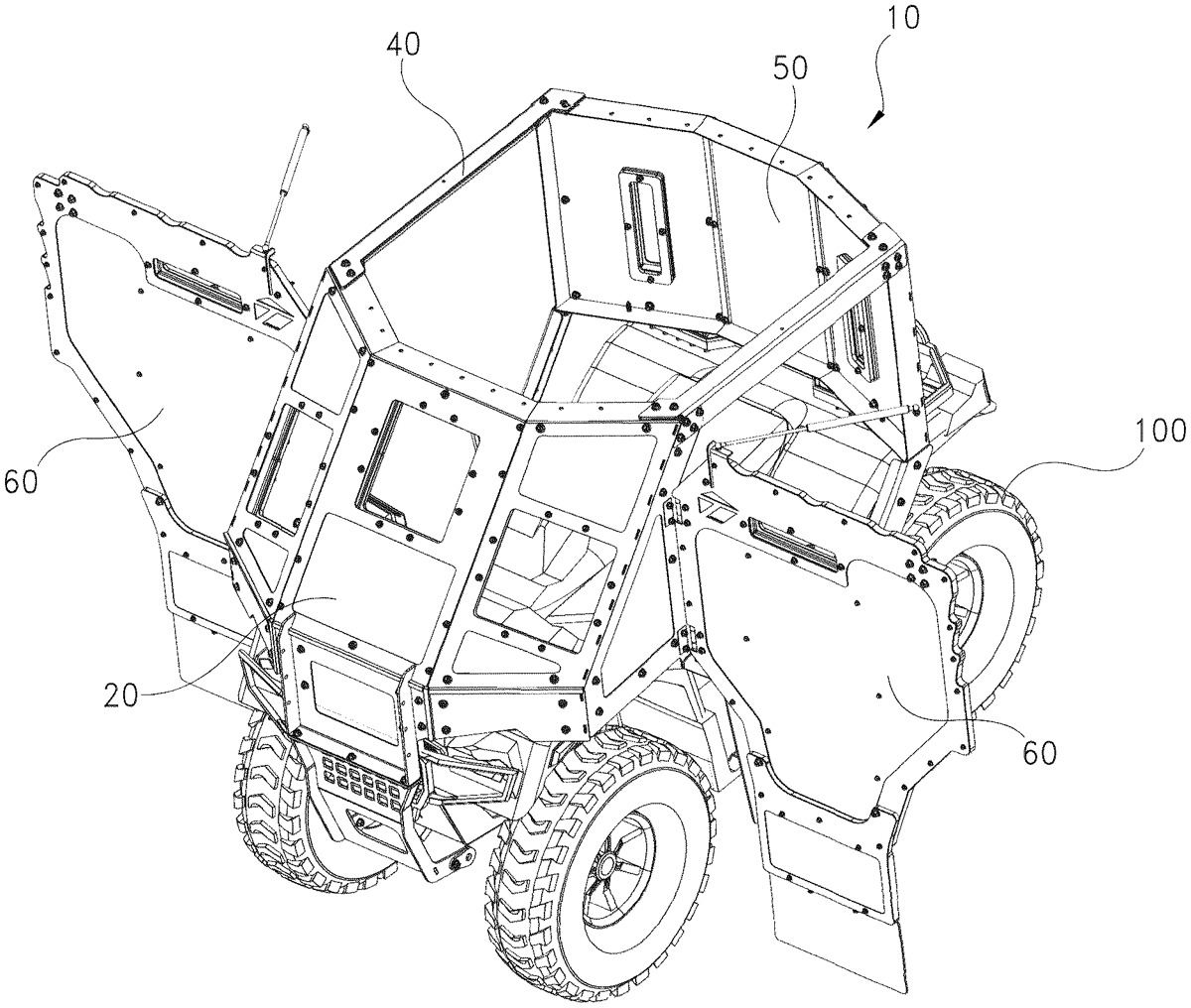
An attachable and detachable surround shield assembly is mountable onto a host vehicle to convert the host vehicle into a protective mobile structure. The surround shield protects the occupant or occupants of the host vehicle from wind or debris and is made of a ballistic material that resists bullets, projectiles, and the like. Optionally, a rear platform mounted to the vehicle provides for the protected advance of multiple people. The surround shield includes hinged door panels that may be opened to allow for lateral protection of responders whether the vehicle is stopped or in motion.
Mar 3, 2026
A floating barrier system has a plurality of connected floating barrier units. Capture net segments are positioned on the floating barrier units by support post members, forming a barrier to vessel passage. Lanyards attach the ends of the capture net segments to the floating barrier units. Upon a vessel striking the capture net segments with sufficient force, the capture nets detach from the support post members and/or pull the support post members over, and the forces from the vessel are transferred via the lanyards to the floating barrier unit. The vessel is prevented from fully passing over the floating barrier unit, thus itself forming a barrier to passage by other vessels.
Mar 3, 2026
In a MEFP warhead detonation of the main charge is controlled to provide elevated pressure at multiple locations on the back surface of the liner to cut the liner and to form and propel forward a plurality of EFPs. An initiation system is configured for multi-point initiation of a plurality of booster charges to detonate the main charge to produce a plurality of detonation waves that constructively interfere at multiple locations on the back surface of the liner to form pressure hot spots that cut the liner and to form and propel forward a plurality of EFPs. In different embodiments, the elevated pressures are between 110% and 200% of the detonation pressure at the front of an individual detonation wave. The liner may, for example, be a flat plate or a include a plurality of dimples in which case the boosters are aligned to the center of the dimples.
Mar 3, 2026
A warhead includes a casing having a periphery wall that extends along a central axis from a forward end of the casing to a rearward end of the casing. The casing defines a cavity configured to contain an explosive material, wherein the forward end of the casing includes a first thread pattern configured to engage a guidance system casing, and the rearward end of the casing includes a second thread pattern configured to engage a propulsion system casing. A first row of fragments is arranged along a first section of the periphery wall of the casing. A plurality of second rows of fragments is rearward of the first row of fragments and arranged along a second section of the periphery wall of the casing. In an example, each of the first and second sections tapers inward towards the central axis as it extends toward the forward end of the casing.
Mar 3, 2026
An aeromechanically stable sabot system that includes a center of gravity that is placed forward of an aerodynamic center of the aeromechanically stable sabot system when in steady-state flight. By placing the center of gravity forwards of the aerodynamic center, the sabot system exhibits positive longitudinal and directional stability. To illustrate, the sabot system and/or portions thereof will return to stable flight after being disturbed in pitch (vertically or about a transverse horizontal axis) or yaw (side to side or about a vertical axis) when traveling horizontally.
Mar 3, 2026
A roll decoupling joint is provided for connecting a rocket motor to a payload. The joint includes a payload adapter, a motor sleeve, a rotational separator and a fastener. The adapter includes an annular socket and a cylindrical core. The socket is bounded by an opening lip and a bulkhead. The payload inserts into the socket through the lip. The core extends axially from the bulkhead opposite the lip. The sleeve is annularly axi-symmetric and inserts into the motor. This sleeve is disposed adjacent to the adapter and around the core supported by the separator. The fastener secures the core to the separator. In various embodiments, the separator constitutes a pair of bearings, and the fastener is a threaded bolt.
Mar 3, 2026
Mar 3, 2026