US12590778 - String-unloading apparatus of a crossbow
The patent describes a string-unloading apparatus for a crossbow that allows a user to operate the safety and trigger assembly with one hand using a cocking device. The apparatus includes a complex system of components such as a trigger unit, string-hooking unit, and unloading unit, all designed to facilitate the safe and efficient discharge of the crossbow’s string.
Claim 1
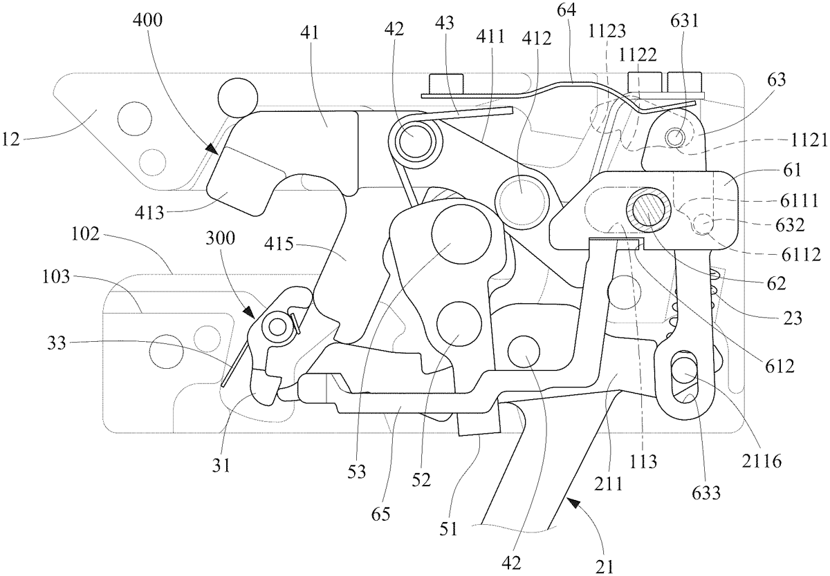
1 . A string-unloading apparatus comprising: a box 100 connected to a barrel of a crossbow, wherein the box 100 comprises: a chamber 101 in the box 100 ; two fletching-receiving slits 102 in communication with the chamber 101 ; a nock-receiving hole 103 in communication with the fletching-receiving slits 102 ; a trigger-receiving slot 104 in communication with the chamber 101 ; an irregular hole 112 cut in an internal portion of the box 100 and in communication with the chamber 101 , wherein the irregular hole 112 comprises a first recess 1121 , a second recess 1122 and a third recess 1123 ; a confining orifice 113 in communication with the chamber 101 ; a pusher-receiving groove 114 cut in another internal portion of the box 100 and in communication with the chamber 101 and the confining orifice 113 ; a trigger unit 200 comprising: a trigger 21 extending from the chamber 101 via the trigger-receiving slot 104 and comprising a first section formed with a bore 2115 and a second section formed with a protuberance 2116 ; a trigger-biasing spring 23 comprising an end in contact with an internal portion of the box 10 and another end in contact with the first section of the trigger 21 , thereby pivoting the second section of the trigger 21 upward; a string-hooking unit 400 comprising: a hook 41 comprising: a shank 411 comprising an orifice 4111 , a boss 412 in vicinity of an end, and a claw 413 extending from another end; a stopping portion 415 extending from a middle section of the shank 411 into the bore 2115 of the trigger 21 ; a shaft 42 extending throughout the third orifice 4111 to pivotally connect the hook 41 to the box 100 ; a hook-biasing spring 43 extending around the shaft 42 and comprising an end in contact with an internal portion of the box 100 and another end in contact with the stopping portion 415 , thereby lifting the claw 413 ; an unloading unit 600 comprising: a pusher 61 movable in the pusher-receiving groove 114 and comprising an end for abutment against the boss 412 and a stepped pocket 611 near another end, wherein the stepped pocket 611 comprises a shallow portion 6111 and a deep portion 6112 ; a handle 62 comprising an end connected to the pusher 61 and another end extending from the chamber 101 via the confining orifice 113 ; an internal connector 63 comprising: a first pivot 631 extending from a side of the internal connector 63 and movable between the first and third recesses 1121 , 1123 via the second recess 1122 , wherein the shank 411 is operable to lift the first pivot 631 to the third recess 1123 from the second recess 1122 ; a second pivot 632 extending from another side of the internal connector 63 and movable between the shallow and deep portions 6111 , 6112 of the stepped pocket 611 ; a slot 633 for receiving the protuberance 2116 of the trigger 21 to selectively actuate the trigger 21 ; a leaf spring 64 comprising a rectilinear section connected to the box 100 and a bent section in contact with an upper section of the internal connector 63 , thereby moving the first pivot 631 between the first and third recesses 1121 , 1123 via the second recess 1122 . a box 100 connected to a barrel of a crossbow, wherein the box 100 comprises: a chamber 101 in the box 100 ; two fletching-receiving slits 102 in communication with the chamber 101 ; a nock-receiving hole 103 in communication with the fletching-receiving slits 102 ; a trigger-receiving slot 104 in communication with the chamber 101 ; an irregular hole 112 cut in an internal portion of the box 100 and in communication with the chamber 101 , wherein the irregular hole 112 comprises a first recess 1121 , a second recess 1122 and a third recess 1123 ; a confining orifice 113 in communication with the chamber 101 ; a pusher-receiving groove 114 cut in another internal portion of the box 100 and in communication with the chamber 101 and the confining orifice 113 ; a chamber 101 in the box 100 ; two fletching-receiving slits 102 in communication with the chamber 101 ; a nock-receiving hole 103 in communication with the fletching-receiving slits 102 ; a trigger-receiving slot 104 in communication with the chamber 101 ; an irregular hole 112 cut in an internal portion of the box 100 and in communication with the chamber 101 , wherein the irregular hole 112 comprises a first recess 1121 , a second recess 1122 and a third recess 1123 ; a confining orifice 113 in communication with the chamber 101 ; a pusher-receiving groove 114 cut in another internal portion of the box 100 and in communication with the chamber 101 and the confining orifice 113 ; a trigger unit 200 comprising: a trigger 21 extending from the chamber 101 via the trigger-receiving slot 104 and comprising a first section formed with a bore 2115 and a second section formed with a protuberance 2116 ; a trigger-biasing spring 23 comprising an end in contact with an internal portion of the box 10 and another end in contact with the first section of the trigger 21 , thereby pivoting the second section of the trigger 21 upward; a trigger 21 extending from the chamber 101 via the trigger-receiving slot 104 and comprising a first section formed with a bore 2115 and a second section formed with a protuberance 2116 ; a trigger-biasing spring 23 comprising an end in contact with an internal portion of the box 10 and another end in contact with the first section of the trigger 21 , thereby pivoting the second section of the trigger 21 upward; a string-hooking unit 400 comprising: a hook 41 comprising: a shank 411 comprising an orifice 4111 , a boss 412 in vicinity of an end, and a claw 413 extending from another end; a stopping portion 415 extending from a middle section of the shank 411 into the bore 2115 of the trigger 21 ; a shaft 42 extending throughout the third orifice 4111 to pivotally connect the hook 41 to the box 100 ; a hook-biasing spring 43 extending around the shaft 42 and comprising an end in contact with an internal portion of the box 100 and another end in contact with the stopping portion 415 , thereby lifting the claw 413 ; a shank 411 comprising an orifice 4111 , a boss 412 in vicinity of an end, and a claw 413 extending from another end; a stopping portion 415 extending from a middle section of the shank 411 into the bore 2115 of the trigger 21 ; a shaft 42 extending throughout the third orifice 4111 to pivotally connect the hook 41 to the box 100 ; a hook-biasing spring 43 extending around the shaft 42 and comprising an end in contact with an internal portion of the box 100 and another end in contact with the stopping portion 415 , thereby lifting the claw 413 ; an unloading unit 600 comprising: a pusher 61 movable in the pusher-receiving groove 114 and comprising an end for abutment against the boss 412 and a stepped pocket 611 near another end, wherein the stepped pocket 611 comprises a shallow portion 6111 and a deep portion 6112 ; a handle 62 comprising an end connected to the pusher 61 and another end extending from the chamber 101 via the confining orifice 113 ; a pusher 61 movable in the pusher-receiving groove 114 and comprising an end for abutment against the boss 412 and a stepped pocket 611 near another end, wherein the stepped pocket 611 comprises a shallow portion 6111 and a deep portion 6112 ; a handle 62 comprising an end connected to the pusher 61 and another end extending from the chamber 101 via the confining orifice 113 ; an internal connector 63 comprising: a first pivot 631 extending from a side of the internal connector 63 and movable between the first and third recesses 1121 , 1123 via the second recess 1122 , wherein the shank 411 is operable to lift the first pivot 631 to the third recess 1123 from the second recess 1122 ; a second pivot 632 extending from another side of the internal connector 63 and movable between the shallow and deep portions 6111 , 6112 of the stepped pocket 611 ; a slot 633 for receiving the protuberance 2116 of the trigger 21 to selectively actuate the trigger 21 ; a leaf spring 64 comprising a rectilinear section connected to the box 100 and a bent section in contact with an upper section of the internal connector 63 , thereby moving the first pivot 631 between the first and third recesses 1121 , 1123 via the second recess 1122 . a first pivot 631 extending from a side of the internal connector 63 and movable between the first and third recesses 1121 , 1123 via the second recess 1122 , wherein the shank 411 is operable to lift the first pivot 631 to the third recess 1123 from the second recess 1122 ; a second pivot 632 extending from another side of the internal connector 63 and movable between the shallow and deep portions 6111 , 6112 of the stepped pocket 611 ; a slot 633 for receiving the protuberance 2116 of the trigger 21 to selectively actuate the trigger 21 ; a leaf spring 64 comprising a rectilinear section connected to the box 100 and a bent section in contact with an upper section of the internal connector 63 , thereby moving the first pivot 631 between the first and third recesses 1121 , 1123 via the second recess 1122 .
Google Patents
https://patents.google.com/patent/US12590778
USPTO PDF
https://image-ppubs.uspto.gov/dirsearch-public/print/downloadPdf/12590778