US12578169 - Archery sight mounting assembly
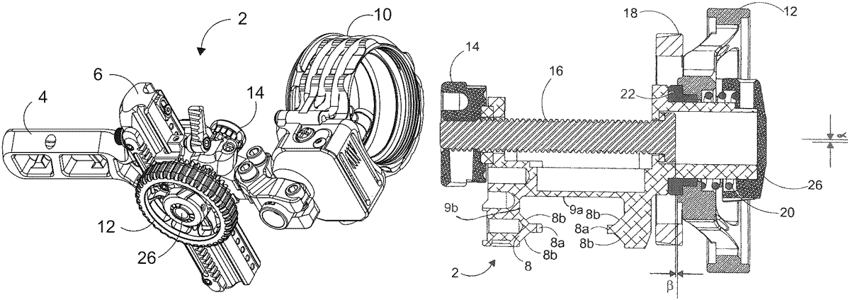
The patent describes an archery sight mounting assembly featuring an elevation rail, an elevation carriage, and a windage assembly that allows for precise adjustments of a scope. The design includes separate adjustment knobs for elevation and windage, enhancing usability for archers.
Claim 1
1 . An archery sight mounting assembly, comprising (a) an elevation rail having a longitudinal axis; (b) an elevation carriage slidably mounted on said elevation rail; (c) an elevation adjustment knob having an outer diameter and an axis of rotation normal to the longitudinal axis of said elevation rail and operable to displace said elevation carriage along said elevation rail; and (d) a windage assembly connected with said elevation carriage for displacing a scope in a direction normal to the longitudinal axis of said elevation rail, said windage assembly including a windage adjustment knob having an axis of rotation parallel and fixed relative to the axis of rotation of said elevation adjustment knob and arranged within an extended outer diameter of and spaced non-concentrically from said elevation adjustment knob. (a) an elevation rail having a longitudinal axis; (b) an elevation carriage slidably mounted on said elevation rail; (c) an elevation adjustment knob having an outer diameter and an axis of rotation normal to the longitudinal axis of said elevation rail and operable to displace said elevation carriage along said elevation rail; and (d) a windage assembly connected with said elevation carriage for displacing a scope in a direction normal to the longitudinal axis of said elevation rail, said windage assembly including a windage adjustment knob having an axis of rotation parallel and fixed relative to the axis of rotation of said elevation adjustment knob and arranged within an extended outer diameter of and spaced non-concentrically from said elevation adjustment knob.
Google Patents
https://patents.google.com/patent/US12578169
USPTO PDF
https://image-ppubs.uspto.gov/dirsearch-public/print/downloadPdf/12578169