US12578167 - Scope turret
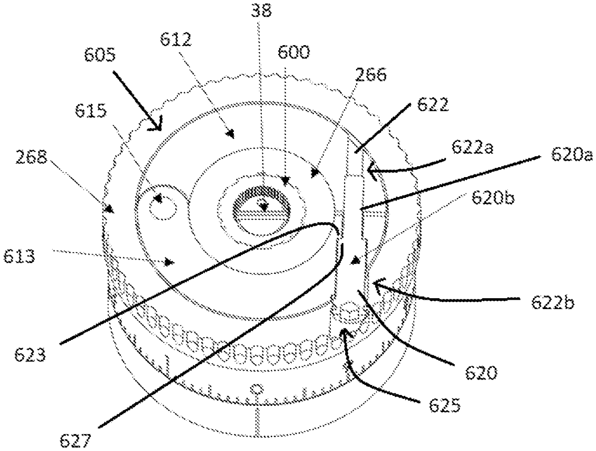
The patent describes a riflescope featuring a movable optical element and a turret that adjusts the optical axis through a turret screw, with a zero-adjustment assembly for precise calibration. This assembly includes a zero-adjustment disc and a locking collar that allows for both free rotation and secured positioning of the optical element.
Claim 1
1 . A riflescope comprising: a scope body; a movable optical element defining an optical axis connected to the scope body; a turret having an outer knob and a turret screw defining a screw axis and operably connected to the optical element for changing the optical axis in response to rotation of the turret screw; and a zero-adjustment assembly contained within the turret and operably interfacing with the turret screw, the zero-adjustment assembly comprising a zero-adjustment disc and a locking collar disposed around a downward facing central shaft of the zero-adjustment disc, wherein the locking collar comprises a first ring half and a second ring half pivotally joined at respective first ends, the locking collar further comprising a channel extending through respective second ends of the first and second ring halves, wherein the zero-adjustment disc is contained in an upper recess of the outer knob. a scope body; a movable optical element defining an optical axis connected to the scope body; a turret having an outer knob and a turret screw defining a screw axis and operably connected to the optical element for changing the optical axis in response to rotation of the turret screw; and a zero-adjustment assembly contained within the turret and operably interfacing with the turret screw, the zero-adjustment assembly comprising a zero-adjustment disc and a locking collar disposed around a downward facing central shaft of the zero-adjustment disc, wherein the locking collar comprises a first ring half and a second ring half pivotally joined at respective first ends, the locking collar further comprising a channel extending through respective second ends of the first and second ring halves, wherein the zero-adjustment disc is contained in an upper recess of the outer knob.
Google Patents
https://patents.google.com/patent/US12578167
USPTO PDF
https://image-ppubs.uspto.gov/dirsearch-public/print/downloadPdf/12578167