US12571607 - Crossbow with pulley assembly
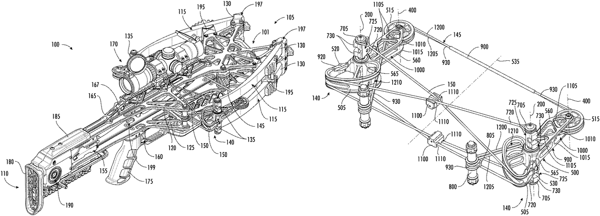
The patent describes a crossbow featuring a flexible limb system and a pulley assembly that enhances the draw mechanism by allowing the draw string to move between released and drawn positions with improved efficiency. The design includes multiple lever arms and pulleys that rotate in coordination to facilitate the drawing of the string, optimizing the crossbow’s performance.
Claim 1
1 . A crossbow, comprising: a first plate; a second plate coupled to the first plate and extending substantially parallel to the first plate, the second plate spaced apart from the first plate; a first upper flexible limb including a first end portion and a second end portion, the first end portion coupled to a first mounting location of the first plate; a first lower flexible limb including a first end portion and a second end portion, the first end portion coupled to a first mounting location of the second plate; a second upper flexible limb including a first end portion and a second end portion, the first end portion coupled to a second mounting location of the first plate; a second lower flexible limb including a first end portion and a second end portion, the first end portion coupled to a second mounting location of the second plate; a draw string, the draw string configured to move between a released position and a drawn position; a first pulley assembly, comprising: a first lever arm rotatably coupled to the second end portion of the first upper flexible limb and the second end portion of the first lower flexible limb, the first lever arm configured to rotate about a first lever arm axis; and a first pulley rotatably coupled to the first lever arm and configured to rotate about a first pulley axis, the first pulley including a first draw string groove, the draw string received by the first draw string groove, the first pulley axis spaced apart from the first lever arm axis; wherein the first lever arm is configured to rotate in a first direction about the first lever arm axis as the draw string is moved from the released position to the drawn position; wherein the first pulley is configured to rotate relative to the first lever arm in the first direction about the first pulley axis as the draw string is moved from the released position to the drawn position; and a second pulley assembly, comprising: a second lever arm rotatably coupled to the second end portion of the second upper flexible limb and the second end portion of the second lower flexible limb, the second lever arm configured to rotate about a second lever arm axis; and a second pulley rotatably coupled to the second lever arm and configured to rotate about a second pulley axis, the second pulley including a second draw string groove, the draw string received by the second draw string groove, the second pulley axis spaced apart from second lever arm axis; wherein the second lever arm is configured to rotate in a second direction about the second lever arm axis as the draw string is moved from the released position to the drawn position; wherein the second pulley is configured to rotate relative to the second lever arm in the second direction about the second pulley axis as the draw string is moved from the released position to the drawn position. a first plate; a second plate coupled to the first plate and extending substantially parallel to the first plate, the second plate spaced apart from the first plate; a first upper flexible limb including a first end portion and a second end portion, the first end portion coupled to a first mounting location of the first plate; a first lower flexible limb including a first end portion and a second end portion, the first end portion coupled to a first mounting location of the second plate; a second upper flexible limb including a first end portion and a second end portion, the first end portion coupled to a second mounting location of the first plate; a second lower flexible limb including a first end portion and a second end portion, the first end portion coupled to a second mounting location of the second plate; a draw string, the draw string configured to move between a released position and a drawn position; a first pulley assembly, comprising: a first lever arm rotatably coupled to the second end portion of the first upper flexible limb and the second end portion of the first lower flexible limb, the first lever arm configured to rotate about a first lever arm axis; and a first pulley rotatably coupled to the first lever arm and configured to rotate about a first pulley axis, the first pulley including a first draw string groove, the draw string received by the first draw string groove, the first pulley axis spaced apart from the first lever arm axis; wherein the first lever arm is configured to rotate in a first direction about the first lever arm axis as the draw string is moved from the released position to the drawn position; wherein the first pulley is configured to rotate relative to the first lever arm in the first direction about the first pulley axis as the draw string is moved from the released position to the drawn position; and a first lever arm rotatably coupled to the second end portion of the first upper flexible limb and the second end portion of the first lower flexible limb, the first lever arm configured to rotate about a first lever arm axis; and a first pulley rotatably coupled to the first lever arm and configured to rotate about a first pulley axis, the first pulley including a first draw string groove, the draw string received by the first draw string groove, the first pulley axis spaced apart from the first lever arm axis; wherein the first lever arm is configured to rotate in a first direction about the first lever arm axis as the draw string is moved from the released position to the drawn position; wherein the first pulley is configured to rotate relative to the first lever arm in the first direction about the first pulley axis as the draw string is moved from the released position to the drawn position; and a second pulley assembly, comprising: a second lever arm rotatably coupled to the second end portion of the second upper flexible limb and the second end portion of the second lower flexible limb, the second lever arm configured to rotate about a second lever arm axis; and a second pulley rotatably coupled to the second lever arm and configured to rotate about a second pulley axis, the second pulley including a second draw string groove, the draw string received by the second draw string groove, the second pulley axis spaced apart from second lever arm axis; wherein the second lever arm is configured to rotate in a second direction about the second lever arm axis as the draw string is moved from the released position to the drawn position; wherein the second pulley is configured to rotate relative to the second lever arm in the second direction about the second pulley axis as the draw string is moved from the released position to the drawn position. a second lever arm rotatably coupled to the second end portion of the second upper flexible limb and the second end portion of the second lower flexible limb, the second lever arm configured to rotate about a second lever arm axis; and a second pulley rotatably coupled to the second lever arm and configured to rotate about a second pulley axis, the second pulley including a second draw string groove, the draw string received by the second draw string groove, the second pulley axis spaced apart from second lever arm axis; wherein the second lever arm is configured to rotate in a second direction about the second lever arm axis as the draw string is moved from the released position to the drawn position; wherein the second pulley is configured to rotate relative to the second lever arm in the second direction about the second pulley axis as the draw string is moved from the released position to the drawn position.
Google Patents
https://patents.google.com/patent/US12571607
USPTO PDF
https://image-ppubs.uspto.gov/dirsearch-public/print/downloadPdf/12571607