US12571606 - Muzzle flash simulator and light track generation method
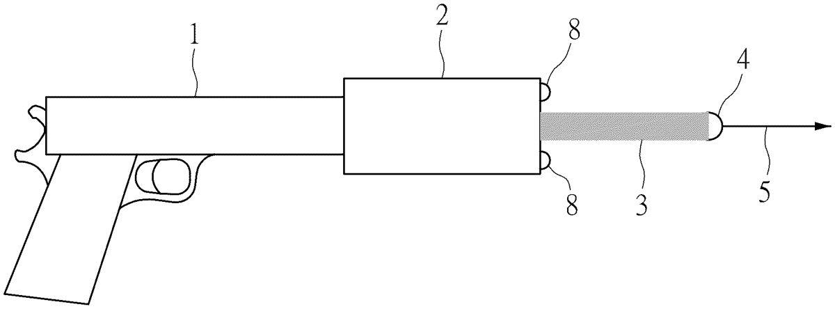
The patent describes a muzzle flash simulator designed for toy air guns, featuring a projectile channel and sensors that trigger light-emitting elements to create a colorful light track corresponding to the projectile’s trajectory. The controller manages the light sources’ operation, ensuring they emit varying colors in a periodic manner based on the projectile’s passage through the channel.
Claim 1
1 . A muzzle flash simulator configured to be installed at a muzzle of a toy air gun, the muzzle flash simulator comprising: a projectile channel provided inside the muzzle flash simulator, wherein the projectile channel is coaxial with a flight trajectory of a projectile; at least one projectile sensor connected to a controller and configured to transmit a trigger signal to the controller when detecting the projectile passes through the projectile channel; wherein the controller is preset to output at least two control signals that periodically change according to the trigger signal; and at least one group of flash simulation light sources connected to the controller, wherein the at least one group of flash simulation light sources includes at least two light-emitting elements having different colors, and the light-emitting elements are configured to periodically emit lights having different colors to the projectile according to the control signals to form a light track; wherein the controller includes: a signal generator circuit preset to output the at least two control signals that periodically change to correspondingly control turn-on, turn-off and luminous brightness of the light-emitting elements having different colors; wherein a ratio of a positive voltage duration of the control signal to a period within a cycle is constant; wherein the positive voltage duration is calculated by the following formula: a projectile channel provided inside the muzzle flash simulator, wherein the projectile channel is coaxial with a flight trajectory of a projectile; at least one projectile sensor connected to a controller and configured to transmit a trigger signal to the controller when detecting the projectile passes through the projectile channel; wherein the controller is preset to output at least two control signals that periodically change according to the trigger signal; and at least one group of flash simulation light sources connected to the controller, wherein the at least one group of flash simulation light sources includes at least two light-emitting elements having different colors, and the light-emitting elements are configured to periodically emit lights having different colors to the projectile according to the control signals to form a light track; wherein the controller includes: a signal generator circuit preset to output the at least two control signals that periodically change to correspondingly control turn-on, turn-off and luminous brightness of the light-emitting elements having different colors; wherein a ratio of a positive voltage duration of the control signal to a period within a cycle is constant; wherein the positive voltage duration is calculated by the following formula: 3 T / 2 n where T is the period, T is less than 0.1 seconds, n is a number of colors of the light-emitting element, and n is greater than 1. where T is the period, T is less than 0.1 seconds, n is a number of colors of the light-emitting element, and n is greater than 1.
Google Patents
https://patents.google.com/patent/US12571606
USPTO PDF
https://image-ppubs.uspto.gov/dirsearch-public/print/downloadPdf/12571606