US12546570 - Firearm optics mount
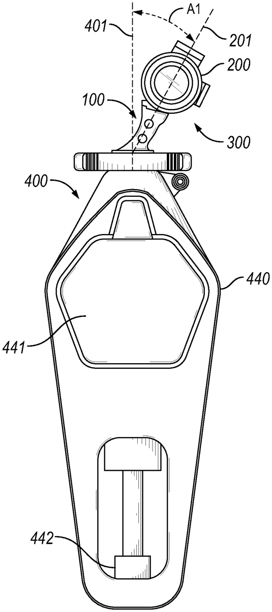
The patent describes a canted firearm optics mount that positions an optic device at an angle between 5 and 30 degrees from the vertical alignment above the barrel, allowing for improved sighting when the firearm is held vertically. This mount includes a base, two supports, and rings for securing a rifle scope, ensuring that the optic’s bullet drop feature aligns with the barrel’s centerline when the firearm is canted.
Claim 1
1 . A mount comprising: a base configured to secure to a firearm above a barrel of said firearm when said firearm is in a vertical position; a first support secured to said base at a proximal end of said first support, wherein said first support extends away from said base; a first ring secured to a distal end of said first support and configured to secure a rifle scope, wherein said first support positions said first ring in a way such that a first centerline extending from said proximal end of said first support through a center of said first ring is offset at an angle between 5 degrees and 30 degrees from a vertical axis of said firearm when said firearm is in said vertical position; a second support secured to said base at a proximal end of said second support, wherein said second support extends away from said base; and a second ring secured to a distal end of said first support and configured to secure said rifle scope, wherein said second support positions said second ring in a way such that a second centerline extending from said proximal end of said second support through a center of said second ring is offset at an angle between 5 degrees and 30 degrees from said vertical axis of said firearm when said firearm is in said vertical position. a base configured to secure to a firearm above a barrel of said firearm when said firearm is in a vertical position; a first support secured to said base at a proximal end of said first support, wherein said first support extends away from said base; wherein said first support extends away from said base; a first ring secured to a distal end of said first support and configured to secure a rifle scope, wherein said first support positions said first ring in a way such that a first centerline extending from said proximal end of said first support through a center of said first ring is offset at an angle between 5 degrees and 30 degrees from a vertical axis of said firearm when said firearm is in said vertical position; wherein said first support positions said first ring in a way such that a first centerline extending from said proximal end of said first support through a center of said first ring is offset at an angle between 5 degrees and 30 degrees from a vertical axis of said firearm when said firearm is in said vertical position; a second support secured to said base at a proximal end of said second support, wherein said second support extends away from said base; and wherein said second support extends away from said base; and a second ring secured to a distal end of said first support and configured to secure said rifle scope, wherein said second support positions said second ring in a way such that a second centerline extending from said proximal end of said second support through a center of said second ring is offset at an angle between 5 degrees and 30 degrees from said vertical axis of said firearm when said firearm is in said vertical position. wherein said second support positions said second ring in a way such that a second centerline extending from said proximal end of said second support through a center of said second ring is offset at an angle between 5 degrees and 30 degrees from said vertical axis of said firearm when said firearm is in said vertical position.
Google Patents
https://patents.google.com/patent/US12546570
USPTO PDF
https://image-ppubs.uspto.gov/dirsearch-public/print/downloadPdf/12546570