US12523439 - Firearm suppressor
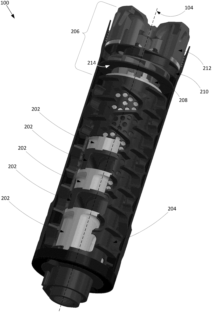
The patent describes a firearm suppressor featuring a series of stackable fluid redirectors with vanes that can direct fluid flow in either a clockwise or counterclockwise direction. Each redirector has a conical annular base designed to facilitate the nesting of adjacent redirectors and includes features for fixed positioning and fluid flow management within the suppressor.
Claim 1
1 . A firearm suppressor comprising: a plurality of fluid redirectors, each of the plurality of fluid redirectors comprising vanes configured to direct a fluid flow in one of either a clockwise or counterclockwise direction, where the plurality of fluid redirectors comprises at least one fluid redirector configured to direct the fluid flow in a clockwise direction, and at least one fluid redirector configured to direct the fluid flow in a counterclockwise direction; and an outer tube disposed around the plurality of fluid redirectors that is configured to define at least one chamber between at least one of the plurality of fluid redirectors and the outer tube to allows fluid flow between the at least one of the plurality of fluid redirectors and an adjacent fluid redirector, and where the rotational position of at least one of the plurality of fluid redirectors is fixed with respect to the outer tube, and where each of the plurality of fluid redirectors comprises: an annular base that tapers to an opening in a center of the annular base, the annular base forming a substantially conical shape; a locating tab extending from at least one of the vanes; and at least one positioning notch formed in the annular base and configured to receive a locating tab of an adjacent fluid redirector. a plurality of fluid redirectors, each of the plurality of fluid redirectors comprising vanes configured to direct a fluid flow in one of either a clockwise or counterclockwise direction, where the plurality of fluid redirectors comprises at least one fluid redirector configured to direct the fluid flow in a clockwise direction, and at least one fluid redirector configured to direct the fluid flow in a counterclockwise direction; and an outer tube disposed around the plurality of fluid redirectors that is configured to define at least one chamber between at least one of the plurality of fluid redirectors and the outer tube to allows fluid flow between the at least one of the plurality of fluid redirectors and an adjacent fluid redirector, and where the rotational position of at least one of the plurality of fluid redirectors is fixed with respect to the outer tube, and where each of the plurality of fluid redirectors comprises: an annular base that tapers to an opening in a center of the annular base, the annular base forming a substantially conical shape; a locating tab extending from at least one of the vanes; and at least one positioning notch formed in the annular base and configured to receive a locating tab of an adjacent fluid redirector. an annular base that tapers to an opening in a center of the annular base, the annular base forming a substantially conical shape; a locating tab extending from at least one of the vanes; and at least one positioning notch formed in the annular base and configured to receive a locating tab of an adjacent fluid redirector.
Google Patents
https://patents.google.com/patent/US12523439
USPTO PDF
https://image-ppubs.uspto.gov/dirsearch-public/print/downloadPdf/12523439