US12516908 - Sighting systems, components, and methods
The patent describes a modular sighting system for projectile launching devices that includes interchangeable components such as sight receivers and bases, allowing for customizable configurations. The design features structures that ensure proper alignment and secure attachment of the sighting components, enhancing usability and versatility.
Claim 1
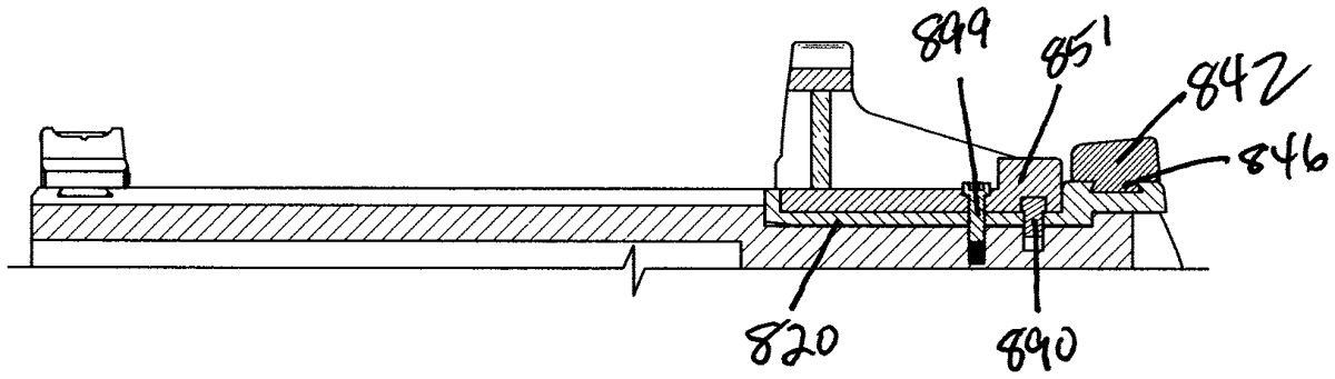
1 . A sight system for a projectile launching device having a longitudinal axis having a front direction and a rear direction, the sight system comprising: a sighting component comprising a first through hole and a first pinhole; a base comprising a generally planar first surface, a generally planar second surface configured as a recess disposed between a first end of the base and a second end of the base, a second through hole extending through the base from the first surface to the second surface, a second pinhole extending through the base from the first surface to the second surface, and a protrusion disposed at the first end of the base; a sight receiver comprising a generally planar third surface, a slot disposed in a wall of the sight receiver located toward the front direction of the longitudinal axis, a tapped boring disposed in the third surface, and an third pinhole disposed in the third surface; a fastener; and a pin; the sight system having an assembled configuration in which: the first surface and the third surface are generally parallel and adjacent, with the protrusion disposed in the slot, the sighting component is disposed along the second surface in the recess, the sighting component and the base are attached to sight receiver by the fastener extending through the first through hole and the second through hole into the tapped boring, and the pin is disposed in first pinhole, the second pinhole, and the third pinhole. a sighting component comprising a first through hole and a first pinhole; a base comprising a generally planar first surface, a generally planar second surface configured as a recess disposed between a first end of the base and a second end of the base, a second through hole extending through the base from the first surface to the second surface, a second pinhole extending through the base from the first surface to the second surface, and a protrusion disposed at the first end of the base; a generally planar first surface, a generally planar second surface configured as a recess disposed between a first end of the base and a second end of the base, a second through hole extending through the base from the first surface to the second surface, a second pinhole extending through the base from the first surface to the second surface, and a protrusion disposed at the first end of the base; a sight receiver comprising a generally planar third surface, a slot disposed in a wall of the sight receiver located toward the front direction of the longitudinal axis, a tapped boring disposed in the third surface, and an third pinhole disposed in the third surface; a generally planar third surface, a slot disposed in a wall of the sight receiver located toward the front direction of the longitudinal axis, a tapped boring disposed in the third surface, and an third pinhole disposed in the third surface; a fastener; and a pin; the sight system having an assembled configuration in which: the first surface and the third surface are generally parallel and adjacent, with the protrusion disposed in the slot, the sighting component is disposed along the second surface in the recess, the sighting component and the base are attached to sight receiver by the fastener extending through the first through hole and the second through hole into the tapped boring, and the pin is disposed in first pinhole, the second pinhole, and the third pinhole. the first surface and the third surface are generally parallel and adjacent, with the protrusion disposed in the slot, the sighting component is disposed along the second surface in the recess, the sighting component and the base are attached to sight receiver by the fastener extending through the first through hole and the second through hole into the tapped boring, and the pin is disposed in first pinhole, the second pinhole, and the third pinhole.
Google Patents
https://patents.google.com/patent/US12516908
USPTO PDF
https://image-ppubs.uspto.gov/dirsearch-public/print/downloadPdf/12516908