US12498190 - Drum-type magazine used in small firearm
The patent describes a drum-type magazine for small firearms that features a housing with a rear cover, bullet guide parts, and two storage spaces for bullets, along with a mechanism for moving bullets into the insertion part. It includes an operation member with a lifting portion and operation rods that facilitate the rotation of bullet-moving members to load bullets efficiently.
Claim 1
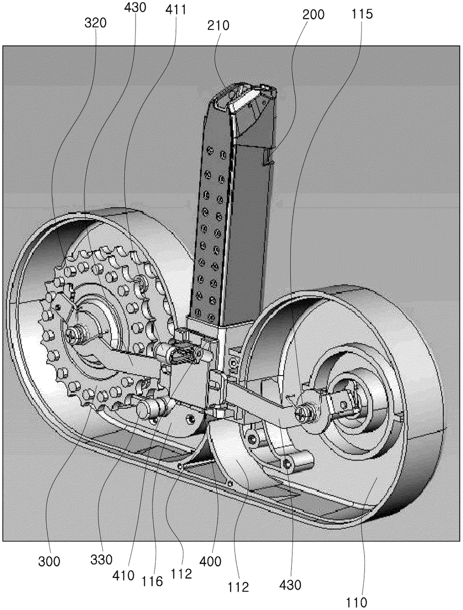
1 . A drum-type magazine used in a firearm comprising: a housing which includes a rear cover, which has an insertion space formed at the central portion thereof and having an inlet formed upward, a pair of bullet guide parts formed below the insertion space, and a first storage space and a second storage space symmetrically formed on both sides facing each other around the insertion space, and a front cover, which is coupled in front of the rear cover to enclose the insertion space, the first storage space, and the second storage space, and has an operation hole penetrating through the central portion thereof; an insertion part of which an open lower end is inserted into the insertion space and connected to the bullet guide parts, and which is inserted into a magazine fitting part of the firearm in a state in which bullets are temporarily held to the top of the insertion part; a pair of bullet-moving members, each of which is rotatably installed with elastic force on a rotational shaft formed at the center of the first storage space and the second storage space, has seating grooves sequentially formed along the outer circumference thereof to allow bullets to be seated, and moves the bullets into the insertion part through the bullet guide part by a rotation in a first direction; and an operation member which includes a lifting portion, which is located in front of a bottom of the insertion part, installed to move up and down, and has an operation lever passing through the operation hole and installed on a front surface thereof, a long-hole bracket, which is installed at a lower portion of the lifting portion and has long holes formed at both facing sides thereof, a pair of operation rods, each of which has one side having a connection pin provided to be rotatably connected to a respective long hole of the long-hole bracket and another side rotatably connected to a respective rotational shaft with elastic force to be rotated depending on an ascending of the lifting portion, and a pair of operation portions, which are installed inside an extended portion of the another side of each operation rod to rotate at a predetermined angle with elastic force to push one of a plurality of operation protrusions annularly protruding at regular intervals around each rotational shaft on a front surface of each bullet-moving member depending on a descending of the lifting portion to rotate the bullet-moving members in a second direction opposite the first direction. a housing which includes a rear cover, which has an insertion space formed at the central portion thereof and having an inlet formed upward, a pair of bullet guide parts formed below the insertion space, and a first storage space and a second storage space symmetrically formed on both sides facing each other around the insertion space, and a front cover, which is coupled in front of the rear cover to enclose the insertion space, the first storage space, and the second storage space, and has an operation hole penetrating through the central portion thereof; an insertion part of which an open lower end is inserted into the insertion space and connected to the bullet guide parts, and which is inserted into a magazine fitting part of the firearm in a state in which bullets are temporarily held to the top of the insertion part; a pair of bullet-moving members, each of which is rotatably installed with elastic force on a rotational shaft formed at the center of the first storage space and the second storage space, has seating grooves sequentially formed along the outer circumference thereof to allow bullets to be seated, and moves the bullets into the insertion part through the bullet guide part by a rotation in a first direction; and an operation member which includes a lifting portion, which is located in front of a bottom of the insertion part, installed to move up and down, and has an operation lever passing through the operation hole and installed on a front surface thereof, a long-hole bracket, which is installed at a lower portion of the lifting portion and has long holes formed at both facing sides thereof, a pair of operation rods, each of which has one side having a connection pin provided to be rotatably connected to a respective long hole of the long-hole bracket and another side rotatably connected to a respective rotational shaft with elastic force to be rotated depending on an ascending of the lifting portion, and a pair of operation portions, which are installed inside an extended portion of the another side of each operation rod to rotate at a predetermined angle with elastic force to push one of a plurality of operation protrusions annularly protruding at regular intervals around each rotational shaft on a front surface of each bullet-moving member depending on a descending of the lifting portion to rotate the bullet-moving members in a second direction opposite the first direction.
Google Patents
https://patents.google.com/patent/US12498190
USPTO PDF
https://image-ppubs.uspto.gov/dirsearch-public/print/downloadPdf/12498190