US12492875 - Rifles comprising a bolt catch device
This patent describes a firearm featuring a bolt catch device integrated into the receiver, which includes a foot, slider, and spring mechanism designed to engage with the firearm’s bolt or bolt carrier. The design allows for enhanced functionality by ensuring the bolt catch can effectively interact with the bolt during operation while maintaining a compact profile within the receiver.
Claim 1
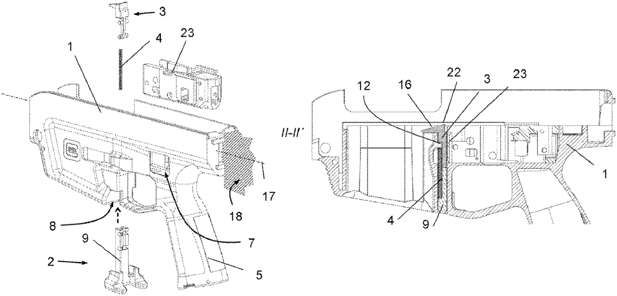
1 . A firearm, including a receiver having a firearm center plane, the firearm comprising: a magazine well defined by the receiver and configured to receive a magazine; a trigger device disposed along the firearm center plane in front of or behind the magazine well; a duct defined in the receiver that, when the firearm is held horizontally, extends substantially vertically between the magazine well and the trigger device; and a bolt catch device disposed in the duct, the bolt catch device having a bolt catch portion configured to interact with a bolt or a bolt carrier of the firearm when in a working position, and when in the working position the bolt catch device engages in the movement path of the bolt; wherein the bolt catch device comprises a foot, a slider, and a spring; the foot has a leg and at least one handle that protrudes laterally beyond a contour of the duct; the leg of the foot defines a groove configured to receive the spring, the groove being defined on the side of the leg facing the magazine well; the leg of the foot defines a socket, the socket being defined on the side of the leg facing the trigger device, wherein the socket has an axis that extends normal to the firearm center plane; the slider includes, on a lower portion thereof when assembled, bearing bolts that are configured to be inserted into and pivoted in the socket; the slider includes, at an upper end thereof, a protrusion that protrudes in a direction of the magazine well beyond the contour of the duct; and the receiver includes an abutment that protrudes into the groove so as to prestress the spring of the bolt catch into a rest position. a magazine well defined by the receiver and configured to receive a magazine; a trigger device disposed along the firearm center plane in front of or behind the magazine well; a duct defined in the receiver that, when the firearm is held horizontally, extends substantially vertically between the magazine well and the trigger device; and a bolt catch device disposed in the duct, the bolt catch device having a bolt catch portion configured to interact with a bolt or a bolt carrier of the firearm when in a working position, and when in the working position the bolt catch device engages in the movement path of the bolt; wherein the bolt catch device comprises a foot, a slider, and a spring; the foot has a leg and at least one handle that protrudes laterally beyond a contour of the duct; the leg of the foot defines a groove configured to receive the spring, the groove being defined on the side of the leg facing the magazine well; the leg of the foot defines a socket, the socket being defined on the side of the leg facing the trigger device, wherein the socket has an axis that extends normal to the firearm center plane; the slider includes, on a lower portion thereof when assembled, bearing bolts that are configured to be inserted into and pivoted in the socket; the slider includes, at an upper end thereof, a protrusion that protrudes in a direction of the magazine well beyond the contour of the duct; and the receiver includes an abutment that protrudes into the groove so as to prestress the spring of the bolt catch into a rest position. the bolt catch device comprises a foot, a slider, and a spring; the foot has a leg and at least one handle that protrudes laterally beyond a contour of the duct; the leg of the foot defines a groove configured to receive the spring, the groove being defined on the side of the leg facing the magazine well; the leg of the foot defines a socket, the socket being defined on the side of the leg facing the trigger device, wherein the socket has an axis that extends normal to the firearm center plane; the slider includes, on a lower portion thereof when assembled, bearing bolts that are configured to be inserted into and pivoted in the socket; the slider includes, at an upper end thereof, a protrusion that protrudes in a direction of the magazine well beyond the contour of the duct; and the receiver includes an abutment that protrudes into the groove so as to prestress the spring of the bolt catch into a rest position.
Google Patents
https://patents.google.com/patent/US12492875
USPTO PDF
https://image-ppubs.uspto.gov/dirsearch-public/print/downloadPdf/12492875