US12480741 - Toggle locking mechanism for a firearm holster
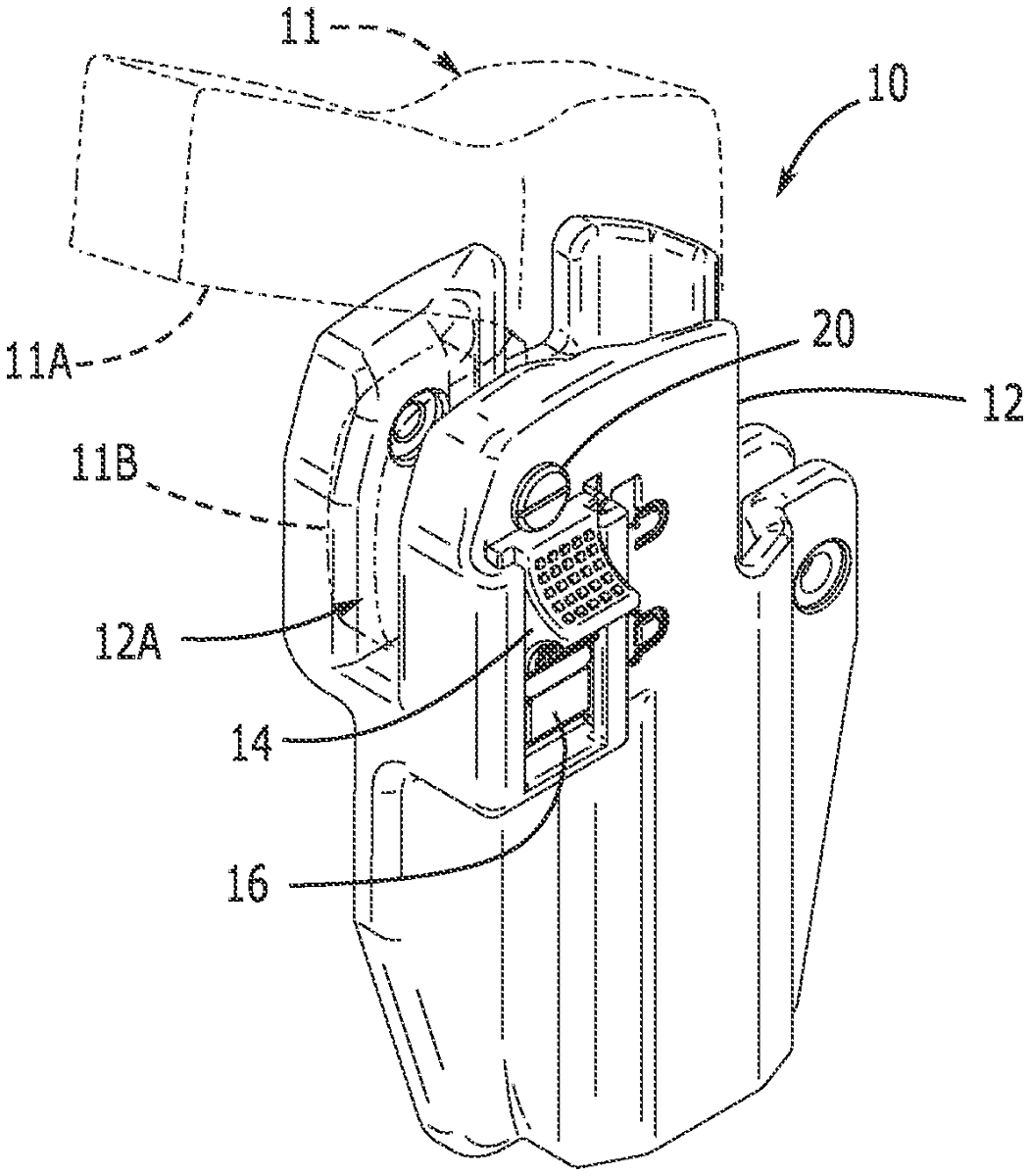
The patent describes a slide-locking mechanism for a firearm holster designed to securely retain a firearm by engaging the trigger guard. It features a plunger and spring system that allows for a locked and unlocked position, ensuring the firearm is held securely when needed and easily released when required.
Claim 1
1 . A slide-locking mechanism for a firearm holster, comprising: a holster dimensioned and configured for retaining a firearm, wherein the firearm defines a gun body having a trigger guard, and wherein the holster defines: a pocket sized and configured for retaining the trigger guard; a lock guide including a spaced-apart pair of slots; a cavity located between the slots; a passage communicating the cavity with the pocket; an inner ledge and an inner wall transverse to the ledge, wherein the inner ledge and wall define a niche located subjacent the cavity and between the slots; a plunger sized and configured for insertion within the cavity; a spring sized and configured for insertion within the niche, wherein the plunger defines a bottom surface and an extension dimensioned and configured for compressing the spring against the inner wall so that the lock plunger is biased in an unlocked position; and a slider defining a spaced-apart pair of slider extensions dimensioned and configured for slidingly engaging within the spaced-apart pair of slots, wherein the plunger defines a first inclined surface, wherein the slider defines a slider inclined surface for slidably engaging the first inclined surface of the plunger, and wherein the plunger is movable within the cavity between a locked position where the bottom surface of the plunger retains the trigger guard within the pocket and the unlocked position where the plunger is spaced from the trigger guard. a holster dimensioned and configured for retaining a firearm, wherein the firearm defines a gun body having a trigger guard, and wherein the holster defines: a pocket sized and configured for retaining the trigger guard; a lock guide including a spaced-apart pair of slots; a cavity located between the slots; a passage communicating the cavity with the pocket; an inner ledge and an inner wall transverse to the ledge, wherein the inner ledge and wall define a niche located subjacent the cavity and between the slots; a pocket sized and configured for retaining the trigger guard; a lock guide including a spaced-apart pair of slots; a cavity located between the slots; a passage communicating the cavity with the pocket; an inner ledge and an inner wall transverse to the ledge, wherein the inner ledge and wall define a niche located subjacent the cavity and between the slots; a plunger sized and configured for insertion within the cavity; a spring sized and configured for insertion within the niche, wherein the plunger defines a bottom surface and an extension dimensioned and configured for compressing the spring against the inner wall so that the lock plunger is biased in an unlocked position; and a slider defining a spaced-apart pair of slider extensions dimensioned and configured for slidingly engaging within the spaced-apart pair of slots, wherein the plunger defines a first inclined surface, wherein the slider defines a slider inclined surface for slidably engaging the first inclined surface of the plunger, and wherein the plunger is movable within the cavity between a locked position where the bottom surface of the plunger retains the trigger guard within the pocket and the unlocked position where the plunger is spaced from the trigger guard.
Google Patents
https://patents.google.com/patent/US12480741
USPTO PDF
https://image-ppubs.uspto.gov/dirsearch-public/print/downloadPdf/12480741