US12467718 - Fast zero adjusting turret for rifle scope
The patent describes a fast zero adjusting turret for rifle scopes, featuring a turret base, a movable adjusting knob, and a central tube with a spline screw and dial to facilitate quick shooting calibration. The design includes a limit cam with a spiral height groove and a turn indicator, allowing operators to easily track adjustments through visual cues.
Claim 1
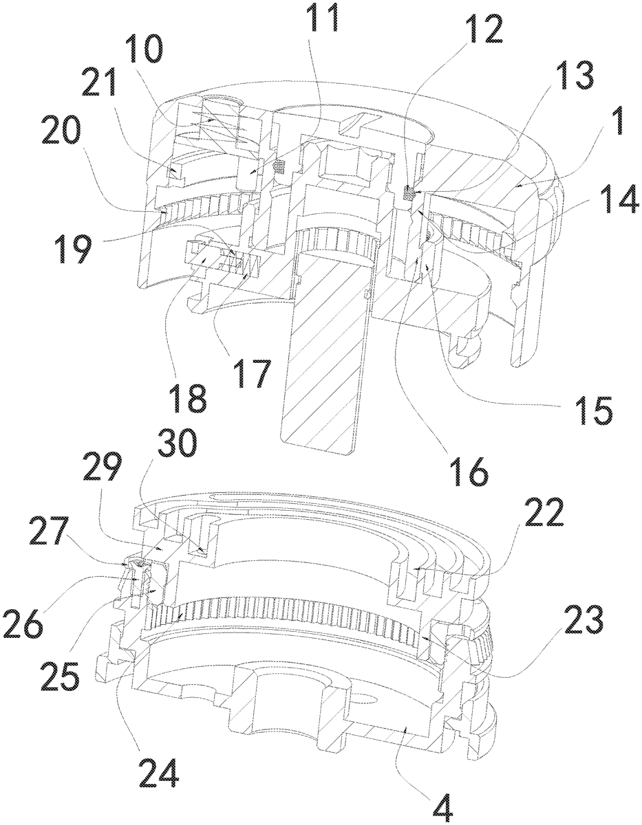
1 . A fast zero adjusting turret for rifle scope, comprising: a turret base ( 4 ) fixed on the scope, a rotatable adjusting knob ( 1 ) movably installed on the turret base ( 4 ), a central tube ( 5 ) vertically penetrating the middle of the bottom surface of the turret base ( 4 ), and a spline screw ( 6 ) that can linearly move up and down the central axis of the central tube ( 5 ); wherein a spline dial ( 7 ) that can rotate with the adjusting knob ( 1 ) is arranged therein, a storing tube ( 8 ) connected to the spline screw ( 6 ) protrudes upward from the top surface of the spline dial ( 7 ), and threads connected to the spline screw ( 6 ) are arranged on the inner peripheral wall of the central tube ( 5 ); a limit cam ( 29 ) fixed relatively to the turret base ( 4 ) and located above the spline dial ( 7 ) is further arranged inside the turret base ( 4 ), a height groove ( 22 ) is opened on the top surface of the limit cam ( 29 ), the height groove ( 22 ) is in spiral shape with multiple spiral turns, and the height of the height groove ( 22 ) with multiple spiral turns is decreased by an equal amount from inside to outside; a countersunk hole ( 30 ) opened on the limit cam ( 29 ) is connected to the bottom surface at the inner end of the height groove ( 22 ), an eccentric float is adhered to the top surface of the limit cam ( 29 ), the top end of which penetrates and extends to the top surface of the adjusting knob ( 1 ), a top reset spring ( 10 ) is movably installed on the eccentric float, on the bottom surface with eccentricity of which an eccentric rod ( 11 ) extending its bottom end to the height groove ( 22 ) and arranged in the countersunk hole ( 30 ) is vertically fixed. a turret base ( 4 ) fixed on the scope, a rotatable adjusting knob ( 1 ) movably installed on the turret base ( 4 ), a central tube ( 5 ) vertically penetrating the middle of the bottom surface of the turret base ( 4 ), and a spline screw ( 6 ) that can linearly move up and down the central axis of the central tube ( 5 ); wherein a spline dial ( 7 ) that can rotate with the adjusting knob ( 1 ) is arranged therein, a storing tube ( 8 ) connected to the spline screw ( 6 ) protrudes upward from the top surface of the spline dial ( 7 ), and threads connected to the spline screw ( 6 ) are arranged on the inner peripheral wall of the central tube ( 5 ); a limit cam ( 29 ) fixed relatively to the turret base ( 4 ) and located above the spline dial ( 7 ) is further arranged inside the turret base ( 4 ), a height groove ( 22 ) is opened on the top surface of the limit cam ( 29 ), the height groove ( 22 ) is in spiral shape with multiple spiral turns, and the height of the height groove ( 22 ) with multiple spiral turns is decreased by an equal amount from inside to outside; a countersunk hole ( 30 ) opened on the limit cam ( 29 ) is connected to the bottom surface at the inner end of the height groove ( 22 ), an eccentric float is adhered to the top surface of the limit cam ( 29 ), the top end of which penetrates and extends to the top surface of the adjusting knob ( 1 ), a top reset spring ( 10 ) is movably installed on the eccentric float, on the bottom surface with eccentricity of which an eccentric rod ( 11 ) extending its bottom end to the height groove ( 22 ) and arranged in the countersunk hole ( 30 ) is vertically fixed.
Google Patents
https://patents.google.com/patent/US12467718
USPTO PDF
https://image-ppubs.uspto.gov/dirsearch-public/print/downloadPdf/12467718