US12460889 - Suppressor connector for firearms
The patent describes a suppressor connector designed to attach a suppressor device to a firearm muzzle, featuring both distal and proximal end threads for secure coupling. It incorporates a flexible pawl with a free-floating proximal end and an outer hood that partially covers the pawl, enhancing the connection’s stability and functionality.
Claim 1
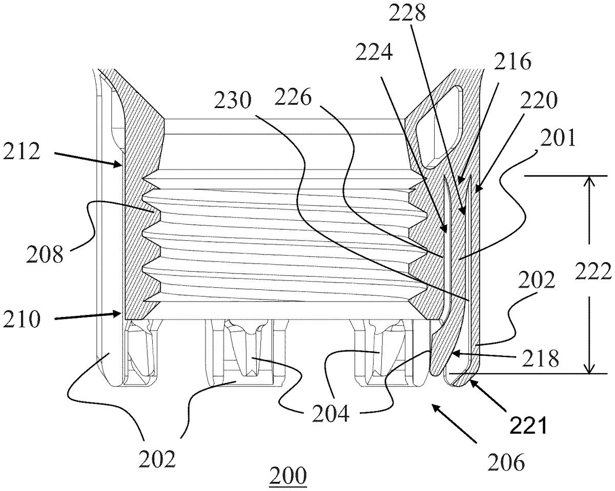
1 . A suppressor connector comprising: a distal end with distal end threads that are operable to couple the suppressor connector to a suppressor device; a proximal end with proximal end threads that are operable to couple the suppressor connector to a muzzle of a firearm, the proximal end threads having a distal thread end and a proximal thread end; at least one flexible pawl having: a distal end coupled to the suppressor connector proximate to the distal thread end of the proximal end threads; a free-floating proximal end that terminates beyond the proximal thread end of the proximal end threads of the suppressor connector; and an engagement face on the free-floating proximal end; and at least one outer hood having: a distal end coupled to the suppressor connector proximate to the distal end of the flexible pawl; and a free-floating proximal end that at least partially covers the free-floating proximal end of the flexible pawl and that extends beyond and substantially parallel to the free-floating proximal end of the flexible pawl. a distal end with distal end threads that are operable to couple the suppressor connector to a suppressor device; a proximal end with proximal end threads that are operable to couple the suppressor connector to a muzzle of a firearm, the proximal end threads having a distal thread end and a proximal thread end; at least one flexible pawl having: a distal end coupled to the suppressor connector proximate to the distal thread end of the proximal end threads; a free-floating proximal end that terminates beyond the proximal thread end of the proximal end threads of the suppressor connector; and an engagement face on the free-floating proximal end; and a distal end coupled to the suppressor connector proximate to the distal thread end of the proximal end threads; a free-floating proximal end that terminates beyond the proximal thread end of the proximal end threads of the suppressor connector; and an engagement face on the free-floating proximal end; and at least one outer hood having: a distal end coupled to the suppressor connector proximate to the distal end of the flexible pawl; and a free-floating proximal end that at least partially covers the free-floating proximal end of the flexible pawl and that extends beyond and substantially parallel to the free-floating proximal end of the flexible pawl. a distal end coupled to the suppressor connector proximate to the distal end of the flexible pawl; and a free-floating proximal end that at least partially covers the free-floating proximal end of the flexible pawl and that extends beyond and substantially parallel to the free-floating proximal end of the flexible pawl.
Google Patents
https://patents.google.com/patent/US12460889
USPTO PDF
https://image-ppubs.uspto.gov/dirsearch-public/print/downloadPdf/12460889