US12429399 - Dynamic acoustic emission in-situ testing device and method for electromagnetic rail launcher
The invention describes a dynamic acoustic emission in-situ testing device for electromagnetic rail launchers, featuring an adjustable support base, guide rails, and multiple acoustic emission sensors. This device aims to analyze the friction damage mechanisms at the armature-rail interface under varying magnetic field conditions.
Claim 1
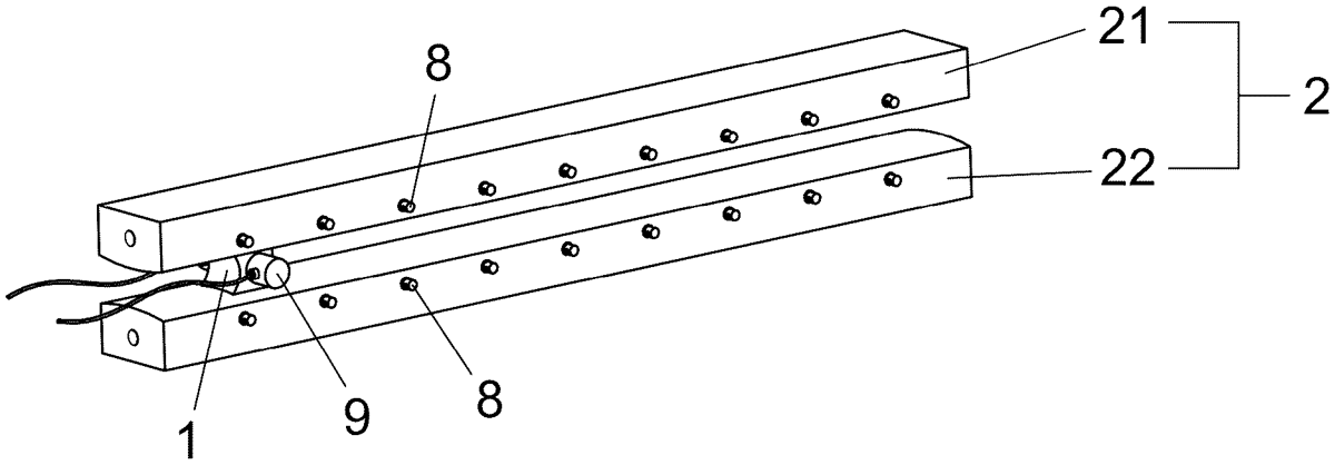
- A dynamic acoustic emission in-situ testing device for an electromagnetic rail launcher, comprising an armature, a guide rail, a support base, bolts, an optical imaging module, an infrared imaging module, static acoustic emission sensors, dynamic acoustic emission sensors and a control module, wherein the support base comprises an upper support base and a lower support base, the upper support base is arranged right above the lower support base at an interval, and a plurality of groups of bolts which are connected to the upper support base and the lower support base are arranged therebetween, so that a distance between the upper support base and the lower support base can be adjusted through the bolts; the guide rail comprises a strip-shaped upper guide rail and a strip-shaped lower guide rail arranged at an interval, the upper guide rail is arranged on the upper support base, the lower guide rail is arranged on the lower support base, the upper guide rail and the lower guide rail are kept parallel on a vertical plane, a plurality of groups of static acoustic emission sensors distributed along the upper guide rail are detachably arranged on the upper guide rail at intervals, and a plurality of groups of static acoustic emission sensors distributed along the lower guide rail are detachably arranged on the lower guide rail at intervals, wherein the static acoustic emission sensors are distributed along two sides of the upper guide rail and the lower guide rail; the armature is arranged on the guide rail, the armature contacts the upper guide rail and the lower guide rail, so that the armature and the guide rail can form a conductive path, the armature can slide along the guide rail, and the armature is detachably provided with the dynamic acoustic emission sensors, wherein the armature is saddle-shaped, and a top surface and a bottom surface of which are parallel to each other and contact the upper guide rail and the lower guide rail respectively; the dynamic acoustic emission sensors are arranged on two sides of the armature; the support base is externally provided with the optical imaging module configured to obtain optical imaging of an area where the armature and the guide rail are located and the infrared imaging module configured to obtain infrared imaging of an area where the armature and the guide rail are located; and the support base is also externally provided with the control module, the control module is in communication connection with the guide rail, the optical imaging module, the infrared imaging module, the static acoustic emission sensors and the dynamic acoustic emission sensors. the guide rail comprises a strip-shaped upper guide rail and a strip-shaped lower guide rail arranged at an interval, the upper guide rail is arranged on the upper support base, the lower guide rail is arranged on the lower support base, the upper guide rail and the lower guide rail are kept parallel on a vertical plane, a plurality of groups of static acoustic emission sensors distributed along the upper guide rail are detachably arranged on the upper guide rail at intervals, and a plurality of groups of static acoustic emission sensors distributed along the lower guide rail are detachably arranged on the lower guide rail at intervals, wherein the static acoustic emission sensors are distributed along two sides of the upper guide rail and the lower guide rail; the armature is arranged on the guide rail, the armature contacts the upper guide rail and the lower guide rail, so that the armature and the guide rail can form a conductive path, the armature can slide along the guide rail, and the armature is detachably provided with the dynamic acoustic emission sensors, wherein the armature is saddle-shaped, and a top surface and a bottom surface of which are parallel to each other and contact the upper guide rail and the lower guide rail respectively; the dynamic acoustic emission sensors are arranged on two sides of the armature; the support base is externally provided with the optical imaging module configured to obtain optical imaging of an area where the armature and the guide rail are located and the infrared imaging module configured to obtain infrared imaging of an area where the armature and the guide rail are located; and the support base is also externally provided with the control module, the control module is in communication connection with the guide rail, the optical imaging module, the infrared imaging module, the static acoustic emission sensors and the dynamic acoustic emission sensors.
Google Patents
https://patents.google.com/patent/US12429399
USPTO PDF
https://image-ppubs.uspto.gov/dirsearch-public/print/downloadPdf/12429399