US12429314 - Adjustable angle three-dimensional target stand
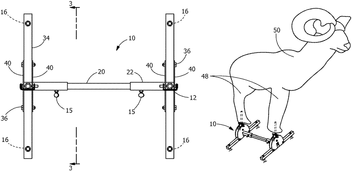
The patent describes an adjustable angle three-dimensional target stand designed for archery and shooting targets, featuring a pair of upright members connected to a platform that allows for angular adjustments of the target. Each upright member includes a peg that can be pivoted to position the target body upright on sloped surfaces, enhancing usability in various shooting scenarios.
Claim 1
- A target stand apparatus for archery, comprising: a pair of upright members disposed at opposing ends of an H-shaped platform; each upright member comprising a peg connected to a peg base; each peg base comprising an upper aperture and a pivot aperture; each peg base attached to at least one dial plate by a pivot bolt inserted through the pivot aperture; each peg base pivotable about the pivot bolt to adjust an angle of the peg relative to the platform; each dial plate including at least two apertures adjacent a peripheral edge of the dial plate and arranged for receiving a locking pin; the platform comprising a pair of frame sections supporting the dial plate associated with each upright member; a hollow receiver portion projecting perpendicular to the frame sections to form the H-shaped platform; a connecting rod insertable into each receiver portion on opposing ends of the connecting rod; the connecting rod slidable within the respective receiver portion for adjusting a spacing between the pair of upright members; wherein each of the pegs being insertable to a target body such that the adjusted angle of the pegs disposes the target body in a generally upright position relative to a sloped surface. a pair of upright members disposed at opposing ends of an H-shaped platform; each upright member comprising a peg connected to a peg base; each peg base comprising an upper aperture and a pivot aperture; each peg base attached to at least one dial plate by a pivot bolt inserted through the pivot aperture; each peg base pivotable about the pivot bolt to adjust an angle of the peg relative to the platform; each dial plate including at least two apertures adjacent a peripheral edge of the dial plate and arranged for receiving a locking pin; the platform comprising a pair of frame sections supporting the dial plate associated with each upright member; a hollow receiver portion projecting perpendicular to the frame sections to form the H-shaped platform; a connecting rod insertable into each receiver portion on opposing ends of the connecting rod; the connecting rod slidable within the respective receiver portion for adjusting a spacing between the pair of upright members; wherein each of the pegs being insertable to a target body such that the adjusted angle of the pegs disposes the target body in a generally upright position relative to a sloped surface.
Google Patents
https://patents.google.com/patent/US12429314
USPTO PDF
https://image-ppubs.uspto.gov/dirsearch-public/print/downloadPdf/12429314